
I think i ruined my board
Forums:
Hello, by mistake i reversed the battery connections to the ThunderBorg board and it is not working anymore. I connected negative from battery to V+ on the board. I saw a sparkle and it smelled like burning for a moment.
Tests i have done:
1) Connect the original battery pack that came with MonsterBorg directly to the lid of the controller and power the PI from the controller:
a) The motor controller turns on.
b) The PI turns on but reboots constantly imediately.
2) Connect the original battery pack that came with MonsterBorg directly to the lid of the controller and power the PI separately (connecting only 4 pins between the controller and PI) :
a) The motor controller turns on.
b) The PI turns on and works correctly.
c) The motors work, and everything seems to work....
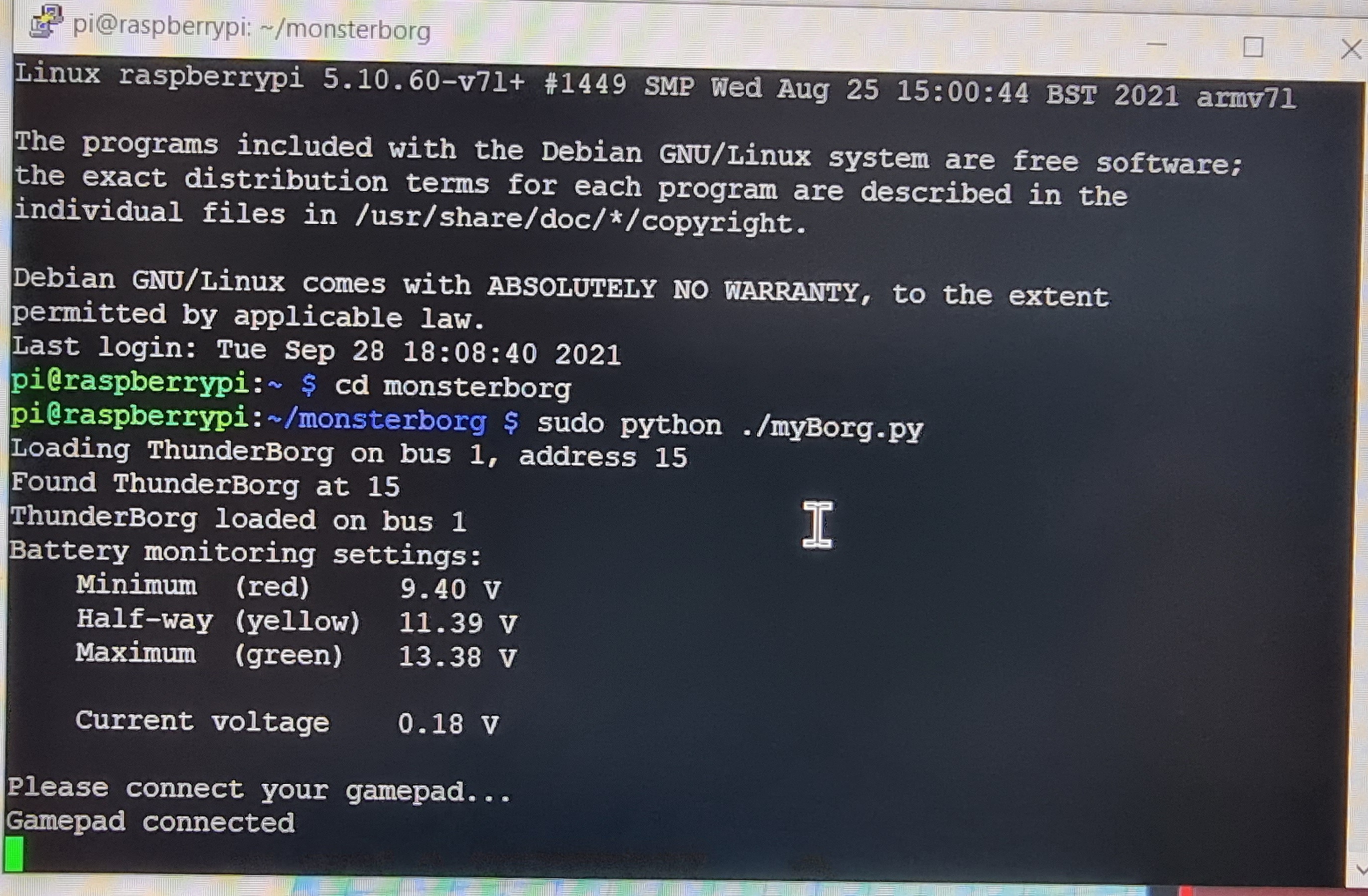
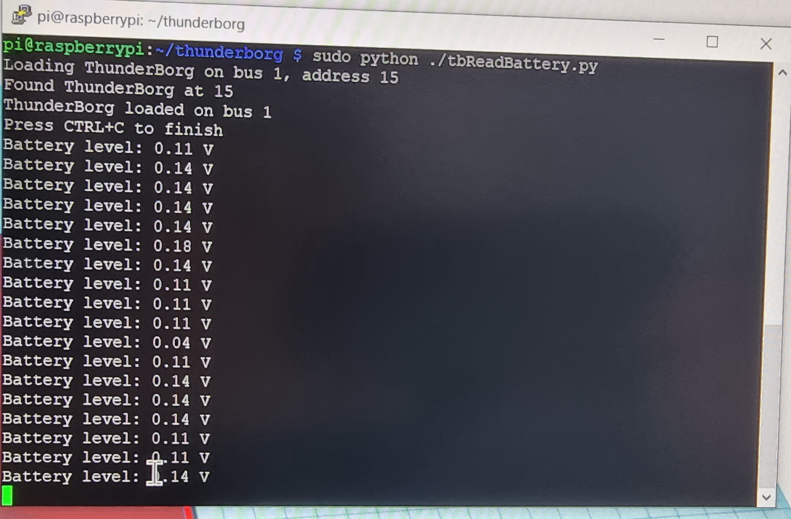
d) Gives wrong voltage readings in both the monsterJoy.py and tbReadBattery.py scripts.
I have not tested to connect the external battery directly to the V+/GND on the controller....
Notes:
The external battery that caused the problem has been working very well for several days now, so i know that the battery is OK.
Attachments:
1) Photo of ThunderBorg controller with highlighted visual sign of the problem.
2) Photo of the external battery with specs.
3) Photo of readings from monsterJoy.py.
4) Photo of readings form tbReadBattery.py.
Is there something i can do to salvage the board???
Thank you


- Log in to post comments


piborg
Wed, 09/29/2021 - 11:13
Permalink
Damaged ThunderBorg
Oh no :(
Since the motors are still controllable there is a chance the board can be repaired, it depends on which components have failed.
Please be advised that it is quite possible that further damage has been done internally to one of the chips on the board that may cause it to fail later. As such it may stop working altogether in the future - PROCEED AT YOUR OWN RISK!
Replacing damaged components will require a soldering iron and a somewhat steady hand. If you are not comfortable soldering I would not recommend attempting a repair yourself.
Good news first, lead-acid batteries like you are using here are fairly resilient to this kind of mistake, it is likely to be completely fine. Keep an eye out for any leaks or bulging just to be safe - if you see any stop using the battery immediately.
The Raspberry Pi repeatedly loosing power is probably because the 5V regulator circuit (the small green board) is damaged. This can be replaced by de-soldering it from the three pins connecting it to the main board and soldering a new board to these pins.
The part number for the regulator is OKI-78SR-5/1.5-W36H-C and they can be found at many major electronics stores (such as RS). We usually keep some replacements in stock but unfortunately we do not have any at this time.
The battery reading is a different story, there are a few different components that may have failed and it looks like they probably took most of the damage based on the photo. Attached is an image labelling the components to check.
You will need access to a multimeter to check most of these problems.
The possible issues that would need fixing are:
These can be checked using the resistance mode on the multimeter.
The correct resistance readings for these are:
(2) - 100 K
(3) - 10 K
(4) - 10 K
A small variation is expected, if the values read 0, open / inf, or very different then the corresponding resistor needs to be replaced.
Measuring resistance between the V+ terminal and the resistor (2) pad closest to it should read as 0. Larger readings indicate the trace is damaged and an open / inf reading would indicate the connection is no longer present.
Both faults can be solved by soldering a wire to that side of resistor (2) and connecting it to the V+ rail somewhere.
Check the resistors first, if they are damaged then this fix may cause more problems!
Basically this chip is intended to limit the voltages carried to the logic chip (6) to the limits for the logic chip.
If it is damaged then it may be restricting the voltages incorrectly.
The monitoring can work without (5), so it is possible to check this by removing the chip from the board entirely and see if things start working.
If it was damaged then it should be replaced with another BAT54S SOT-23.
In this case the internal circuitry for the logic chip has failed and is unable to correctly read voltages now.
This can only be fixed by replacing the chip, unfortunately that also means the board would need to be reprogrammed (which requires a programming tool).
As mentioned at the start there is a risk that there is other hidden damage that my not appear until later. As such using this board after such damage will be at your own risk.
b.bregu@2bconsu...
Wed, 09/29/2021 - 19:00
Permalink
Thank you very much for your
Thank you very much for your prompt and detailed explanation.