
Installation Issues

Forums:
Post here for queries regarding setup problems.
We recommend you try using the troubleshooting instructions here first if you have not already.
Please try to list as much about the problem as you can (OS distribution, versions, motor setup et cetera), the more we know the easier it is to help :)
- Log in to post comments


piborg
Mon, 08/17/2015 - 13:32
Permalink
metalSequence.py not working
Well that is surprising, the script should run the motors for about half a minute on standard settings.
There are a couple of things you can try to see if you can get the script to work.
When removed the motors are prevented from running
sudo killall pythontestMode = TrueThis should quote the settings and perform one move at a time
You should not really need to do this, but it can fix some strange problems:
sudo ./metalSequence.pyIf none of the above works could you tell us the following:
uname -adisplay?pythonfrom the metalborg directory and try the following commands:What do the motors do and what is displayed on the terminal?
sebi82ne
Mon, 08/17/2015 - 15:29
Permalink
1. The tow-pin jumper are
1. The tow-pin jumper are correct fitted on the board and the motors are have enough room and will not be blocked.
2. It run no further scripts.
3. I changed the line 34 in the script and the script continues to run but the motors do not run , see also display output:
pi@raspberrypi ~/metalborg $ sudo ./metalSequence.py
Loading PicoBorg Reverse on bus 1, address 44
Found PicoBorg Reverse at 44
PicoBorg Reverse loaded on bus 1
Current settings are:
timeForward1m = 5.700000
timeSpin360 = 4.800000
Check distance, Press ENTER to start
Drive forward 30cm
Press ENTER to continue
Drive reverse 30cm
Check spinning, Press ENTER to continue
Spinning left
Press ENTER to continue
Spinning Right
Update the settings as needed, then test again or disable test mode
pi@raspberrypi ~/metalborg $
- without the change in script at line 34 , it breaks off very quickly
- pi@raspberrypi ~/metalborg $ uname -a
Linux raspberrypi 3.18.11-v7+ #781 SMP PREEMPT Tue Apr 21 18:07:59 BST 2015 armv7l GNU/Linux
pi@raspberrypi ~/metalborg $
- it run at startup no other scripts
- the other scripts are run but the motors do not run , for example, when I start metalWeb.py I have a picture , the controller can operate but the motors are not running
- pi@raspberrypi ~/metalborg $ sudo python
Python 2.7.3 (default, Mar 18 2014, 05:13:23)
[GCC 4.6.3] on linux2
Type "help", "copyright", "credits" or "license" for more information.
>>> import PicoBorgRev
>>> PBR = PicoBorgRev.PicoBorgRev()
>>> PBR.Init()
Loading PicoBorg Reverse on bus 1, address 44
Found PicoBorg Reverse at 44
PicoBorg Reverse loaded on bus 1
>>> PBR.SetEpoIgnore(True)
>>> PBR.ResetEpo()
>>> PBR.SetMotor1(0.3)
>>> PBR.SetMotor2(0.3)
>>> print PBR.GetDriveFault()
False
>>> PBR.MotorsOff()
>>>
pi@raspberrypi ~/metalborg $
piborg
Tue, 08/18/2015 - 11:58
Permalink
Motors not running
Okay, I cannot see anything wrong from the output so far.
We can do a quick check to see if the board is accepting commands.
If you run these commands and show us the output:
If you have a multimeter it would also help to know the voltages across the screw terminals of the PicoBorg Reverse.
At the end of the sequence above if you could measure the voltage across these terminals:
See the diagram below for the pin names of the screw terminals.
sebi82ne
Wed, 08/19/2015 - 16:19
Permalink
pi@raspberrypi ~/metalborg $
pi@raspberrypi ~/metalborg $ sudo python
Python 2.7.3 (default, Mar 18 2014, 05:13:23)
[GCC 4.6.3] on linux2
Type "help", "copyright", "credits" or "license" for more information.
>>> import PicoBorgRev
>>> PBR = PicoBorgRev.PicoBorgRev()
>>> PBR.Init()
Loading PicoBorg Reverse on bus 1, address 44
Found PicoBorg Reverse at 44
PicoBorg Reverse loaded on bus 1
>>> PBR.SetEpoIgnore(False)
>>> print 'EPO ignore:', PBR.GetEpoIgnore()
EPO ignore: False
>>> PBR.ResetEpo()
>>> print 'EPO tripped:', PBR.GetEpo()
EPO tripped: False
>>> print 'Encoder mode:', PBR.GetEncoderMoveMode()
Encoder mode: False
>>> PBR.SetMotor1(0.3)
>>> PBR.SetMotor2(0.5)
>>> print 'Motor 1 speed:', PBR.GetMotor1()
Motor 1 speed: 0.298039215686
>>> print 'Motor 2 speed:', PBR.GetMotor2()
Motor 2 speed: 0.498039215686
>>>
pi@raspberrypi ~/metalborg $
I could measure with the multimeter no voltage at the terminals.
piborg
Wed, 08/19/2015 - 16:35
Permalink
No power to the motors
It sounds like power is not getting from the battery to the PicoBorg Reverse.
The multimeter should read the current battery voltage between V+ and GND.
If you are getting 0v here it suggests the battery is not properly connected to the board.
The first thing to check is if the batteries are supplying power to the deans connector:
https://www.piborg.org/diddyborg/metaledition/build#step40c
If you get 0v on this connector then you have one of the following problems:
If you get a voltage double check that the red and black cables are connected to the correct pins on the connector.
sebi82ne
Thu, 08/20/2015 - 19:17
Permalink
the voltage at V + and GND is
the voltage at V + and GND is 15.1 ~ 15.3 , if I measure at M1 and M2 , the voltage 0 , no matter what I do.
I have replaced all the batteries and all newly soldered cable and wired and more than twice all tested connections . when I turn diddyborg , also illuminates the red LED on the PicoBorgReverse briefly. when I start, for example, the red LED lights up metalborgFollowBall.py permanently. but no matter what I do, the voltage at M1 and M2 is always zero.
piborg
Fri, 08/21/2015 - 11:31
Permalink
Motors not moving
The behavior of the red LED on PicoBorg Reverse depends on what the script does.
It should turn on briefly when the board is powered to indicate the PicoBorg Reverse has powered up.
When
metalborgFollowBall.pyis running it should only be on if the EPO jumper is removed.When the script ends the LED is left on by this script.
Does
metalborgFollowBall.pykeep running, or does it stop on its own?Can you show us what was printed to the terminal when running
metalborgFollowBall.py?The
metalFollowBall.pyscript is fairly complex and requires many things to work properly.I suggest we stick with either:
runMetalJoy.shif you have a joystick / PS3 controllermetalSequence.pyif you do not have a joystick / PS3 controlleruntil the motors are actually moving.
ben1098
Sun, 10/04/2015 - 13:04
Permalink
lm-sensors site down
Is there an alternative for the site lm-sensors.org?
piborg
Sun, 10/04/2015 - 17:03
Permalink
Website down
When a website is down you can usually view a copy using the Wayback Machine: https://archive.org/web/
Simply enter the site address and click "browse history" to see if they have any copies.
This is also a useful tool if a website has changed and you want to see what used to be on it.
This should be the latest copy they have of lm-sensors.org:
https://web.archive.org/web/http://www.lm-sensors.org/
tbrookes
Sun, 01/03/2016 - 15:02
Permalink
Pi setup on diddyborg - jstest not found
I'm working through setting a Pi 2 up for the diddyborg. I'm using a full installation of Jessie, and have been working through the software setup instructions ok (well sort of). I think I've gott the PS3 controller paired ok with the bluetooth dongle at last after using a new dongle that works with a pi. Before I move on I wanted to double check everything was working ok, so stated looking for jstest. I typed the instructions in the build notes and found nothing. I then checked to see if /dev/imput/js existed and it didn't.
Archlinux suggested I should check which modules were complied in the kernal or being loaded, but I stopped there. I In the messing about with a B/T dongle earlier, I tried to run HCIsomething to and that failed as well (I know it's not part of your notes but the raaspi foundation suggests trying this)
So the current state is I think the PS3 unit is pairing ok, but I can't test it properly as per the notes before adding in the camera. Oh & I did do a run apt-get update and run apt-get upgrade as part of the Jessie installation.
Hints most welcome.
piborg
Mon, 01/04/2016 - 17:27
Permalink
Installing jstest
I believe that jstest is part of the joystick package.
it should be installed by this command:
sudo apt-get install joystickIf the joystick pacakge is not already installed it may be the reason that /dev/input/js0 is not showing up.
tbrookes
Mon, 01/04/2016 - 21:07
Permalink
Thanks for that. I ran that
Thanks for that. I ran that command, it told me that that the latest version was already on the Pi. Trouble is I have no idea where nor how to find it.
piborg
Tue, 01/05/2016 - 09:48
Permalink
I think I might be confused
Is the problem that you do not have jstest, or that the joystick does not seem to be there?
You can check this by using this command:
sudo jstestIf you get this error:
sudo: jstest: command not foundjstest is missing for some reason.
If you get help text instead then jstest is installed.
Could you also try this sequence and tell us what the output is:
ls -l /dev/input/js*philippe.ihuel@...
Tue, 01/19/2016 - 21:22
Permalink
error message / smbus not found
Hi,
I juste received my piborg reverse. Installed the motors ad electronic. Then i followed the following tutorial :
https://www.piborg.org/diddyborg/install
When i try to run ./diddySequence.py i have an error message
Traceback (most recent call last):
File "./diddySequence.py", line 7, inimport PicoBorgRev
File "/home/pi/diddyborg/PicoBorgRev.py", line 30, in
import smbus
ImportError: No module named smbus
i tried to follow instructions regarding python3 smbus things (previously on this topic) but when i get the following file i get 404
wget http://lm-sensors.org/svn/lm-sensors/tags/V2-10-8/kernel/include/i2c-dev.h /Can you help me ? :)
piborg
Tue, 01/19/2016 - 22:25
Permalink
Python 3 smbus module
It looks like the entire 'svn' part of the lm-sensors.org site is unavailable.
I think I have found an equivalent file you can try:
wget http://www.sadaji.net/Firmware/BBB/i2c-dev.hphilippe.ihuel@...
Wed, 01/20/2016 - 20:46
Permalink
Thank you, i did the wget
Thank you, i did the wget then
python3 setup.py build

sudo python3 setup.py install
no error message
But trying again to run the py script, i get the same error.
philippe.ihuel@...
Wed, 01/20/2016 - 22:14
Permalink
Nevermind, it works fine :)
Nevermind, it works fine :)
Thank you
ajalexsmith
Sun, 01/24/2016 - 17:21
Permalink
Help!
Hello i have tried everything on this page to get the piborg reverse to work but i keep getting the same error. Im running a raspberry pi b on the latest raspbian Jessie )
Linux raspberrypi 4.1.13+ #826 PREEMPT Fri Nov 13 20:13:22 GMT 2015 armv6l GNU/Linux). i get the error code !
python: can't open file 'picoborgrev.py': [Errno 2] No such file or directory
I have tried all the previous methods, I have changed the busnumber to zero but still no luck.
lsmod gives me this
pi@raspberrypi:~/picoborgrev $ lsmod
Module Size Used by
cfg80211 499834 0
rfkill 22491 1 cfg80211
evdev 11364 2
snd_bcm2835 22317 3
bcm2835_gpiomem 3703 0
snd_pcm 92581 1 snd_bcm2835
snd_timer 23454 1 snd_pcm
snd 68161 9 snd_bcm2835,snd_timer,snd_pcm
uio_pdrv_genirq 3690 0
uio 10002 1 uio_pdrv_genirq
i2c_bcm2708 6252 0
i2c_dev 6730 0
fuse 91981 3
ipv6 360374 24
the blacklist file is completley blank. any ideas? I really need this for a school project else it's a big fat A-Level F!
edit:- Just tried it on a pi b+ exactly the same issue, that means the only thing that hasn't changed is the board and motors/battery.
ajalexsmith
Mon, 01/25/2016 - 12:00
Permalink
Don't worry it was just the
Don't worry it was just the I2C not being enabled! For some reason despite using the install.sh script it didn't work despite trying it 3 times and on a different Pi. :D all working now and a great board!
piborg
Mon, 01/25/2016 - 12:35
Permalink
That is good
Glad to hear you got it to work in the end.
Usually the procress of enabling the I2C in raspi-config and then running the install script is enough.
tuli
Mon, 03/28/2016 - 12:15
Permalink
PicoBorg Reverse Problem
Hello,
I'm having a problem using the PicoBorg Reverse - every time I run
I recieve the error:
Loading PicoBorg Reverse on bus 1, address 44
Missing PicoBorg Reverse at 44
PicoBorg Reverse was not found
Trying bus 0 instead
Loading PicoBorg Reverse on bus 0, address 44
Traceback (most recent call last):
  File "test.py", line 3, in
    PBR.Init()
  File "/home/pi/picoborgrev/PicoBorgRev.py", line 264, in Init
    self.Init(False)
  File "/home/pi/picoborgrev/PicoBorgRev.py", line 234, in Init
    self.bus = smbus.SMBus(self.busNumber)
IOError: [Errno 2] No such file or directory
I have read through this forum and tried all the suggestions to fix similar problems, yet I'm still having no luck.
The output from
is:
     0  1  2  3  4  5  6  7  8  9  a  b  c  d  e  f
00:          -- -- -- 06 -- -- -- -- -- -- -- -- 0f
10: -- -- -- -- -- -- -- -- 18 -- -- -- -- -- -- --
20: -- 21 -- -- -- -- -- -- -- -- 2a -- -- -- -- --
30: -- -- -- 33 -- -- -- -- -- -- -- -- 3c -- -- --
40: -- -- -- -- -- 45 -- -- -- -- -- -- -- -- 4e --
50: -- -- -- -- -- -- -- 57 -- -- -- -- -- -- -- --
60: 60 -- -- -- -- -- -- -- -- 69 -- -- -- -- -- --
70: -- -- 72 -- -- -- -- --
So it appears the Pi is recognising an i2c device is connected, however it is not recognised as a PicoBorg Reverse, and therefore the Python program cannot detect it.
I have tried this with four Raspberry Pis, (three model 2Bs, and one model 3B), each running the latest version of Raspbian, with no other devices connected (besides the keyboard, mouse, monitor, etc.).
I've also tried swapping the cables for different ones, and I have the same IOError each time. I can confirm it is not the cables that are the problem because there is definitely a connection being made - continuity check with a multimeter.
Any thoughts?
Thanks,
George
piborg
Tue, 03/29/2016 - 11:15
Permalink
Strange i2cdetect result
The output from i2cdetect looks very strange, something is not quite right here.
If you could answer some questions it will help us figure out where the problem is:
i2cdetect -y 1always show the same values?i2cdetect -y 1show when the PicoBorg Reverse is not attached?cd ~/picoborgrev pythonRun these lines:
    import PicoBorgRev
    print PicoBorgRev.ScanForPicoBorgReverse()
What results do you get from the
ScanForPicoBorgReversecommand?tuli
Tue, 03/29/2016 - 12:13
Permalink
i2cdetect
1. The devices plugged into the Pi are: USB mouse, USB bluetooth dongle for keyboard, USB wi-fi dongle, HDMI monitor, USB power supply, PicoBorg Reverse using its six GPIO pins.
2. Running
i2cdetect -y 1gives the output:0 1 2 3 4 5 6 7 8 9 a b c d e f 00: 03 -- -- -- -- -- -- -- -- 0c -- -- -- 10: -- -- -- -- -- 15 -- -- -- -- -- -- -- -- 1e -- 20: -- -- -- -- -- -- -- 27 -- -- -- -- -- -- -- -- 30: 30 -- -- -- -- -- -- -- -- 39 -- -- -- -- -- -- 40: -- -- 42 -- -- -- -- -- -- -- -- 4b -- -- -- -- 50: -- -- -- -- 54 -- -- -- -- -- -- -- -- 5d -- -- 60: -- -- -- -- -- -- 66 -- -- -- -- -- -- -- -- 6f 70: -- -- -- -- -- -- -- --Rebooting the Pi, and running the command again gives the same output.
3. When the PicoBorg Reverse is not attached,
i2cdetect -y 1gives the output:0 1 2 3 4 5 6 7 8 9 a b c d e f 00: -- -- -- -- -- -- -- -- -- -- -- -- -- 10: -- -- -- -- -- -- -- -- -- -- -- -- -- -- -- -- 20: -- -- -- -- -- -- -- -- -- -- -- -- -- -- -- -- 30: -- -- -- -- -- -- -- -- -- -- -- -- -- -- -- -- 40: -- -- -- -- -- -- -- -- -- -- -- -- -- -- -- -- 50: -- -- -- -- -- -- -- -- -- -- -- -- -- -- -- -- 60: -- -- -- -- -- -- -- -- -- -- -- -- -- -- -- -- 70: -- -- -- -- -- -- -- --4. Following the steps you detailed, the
ScanForPicoBorgReversecommand gives the output:piborg
Tue, 03/29/2016 - 12:45
Permalink
PicoBorg Reverse strange i2cdetect
That is interesting, so the i2cdetect is still giving a strange pattern, but different from your previous example.
It does seem like the PicoBorg Reverse might be faulty, but this is a fault we have not seen before.
We test the boards work before they are shipped out, this test includes some I2C communications so I am surprised we did not encounter the same issue.
A couple more questions:
tuli
Tue, 03/29/2016 - 13:00
Permalink
LED
I hadn't realised the i2cdetect output being different between the two examples - perhaps using a different Pi is the cause of that.
The LED comes on briefly when power is connected, as expected.
The LED remains off, i.e. I haven't seen the LED come on afterwards, so I don't think power to the board is a problem.
piborg
Tue, 03/29/2016 - 13:14
Permalink
Faulty PicoBorg Reverse
Well I have to admit this particular problem has me stumped.
It sounds like the on-board logic is having some trouble with the I2C lines, hence the strange address reporting.
Unfortunately we do not have any stock of PicoBorg Reverses at the moment so I cannot send you out a replacement.
What we can do is find the cause of the problem and attempt to repair the board for you.
If you are happy for us to do that all you need to do is post the board back to us.
The address to post the board back to is:
Unit 15, Earith Business Park
Meadow Drove
Earith
Huntingdon
PE28 3QF
If you could also leave a note in the package to explain the board is being returned for repair.
tuli
Tue, 03/29/2016 - 13:26
Permalink
Faulty PicoBorg Reverse
I agree that it sounds like an on-board logic problem.
I would really appreciate it if you can attempt to fix the board - I'll post it to your address.
Thank you very much for your help.
George
piborg
Mon, 04/04/2016 - 15:15
Permalink
Faulty PicoBorg Reverse
I have had a look at the PicoBorg Reverse, there is definitely something wrong with the onboard logic.
Put simply it appears to be sending data when it should not, preventing the I2C from working properly.
I have replaced the logic chip and it is now functioning as intended.
I have tested it with some motors as well as an I2C 'burn-in' type test, all of which now work correctly.
I will send the board back to you at the address on your enclosed letter.
It should be dispatched in the next mail bag, probably tomorrow.
tuli
Mon, 04/04/2016 - 16:17
Permalink
Thank you very much for
Thank you very much for sorting out the problem, and for testing the board.
Shixo87
Wed, 04/13/2016 - 11:59
Permalink
Raspberry Pi3 - Reverse not Found
Hi,
We bought 15 DiddyBorg recently with Raspberry Pi 3 for our lab. I installed all the needed software as recommended before assembly. Now I have two of them not able to find the Reverse while they have exactly the same configuration and wiring. When I try to run the WebUI script I get the error as specified in the screenshot. Actually, one of these two raspies was working fine then after switching off and on again it gave me the same error now!
piborg
Wed, 04/13/2016 - 13:17
Permalink
PicoBorg Reverse was not found
Just to check some common problems:
i2cdetect -y 1on the two DiddyBorgs with the problem?raspi-configand see if that has any effectuname -afrom the terminal?The most likely explanation is that the 3-pin cables are to blame on these two DiddyBorgs.
I believe each of the DiddyBorgs should have had a spare 3-pin cable in the box.
I would suggest that you try changing the 3-pin cable which carries the I2C signals for a spare and see if the problem goes away.
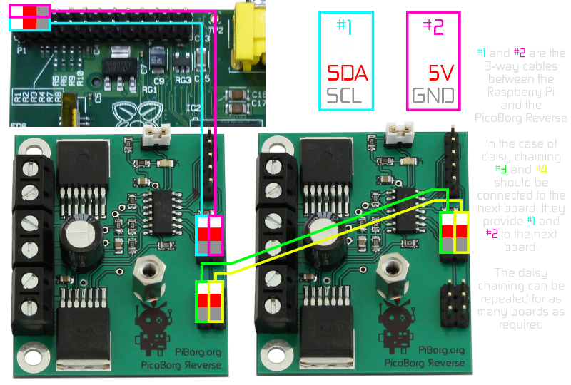
It is the cable which is connected to the pin marked '1' on the PicoBorg Reverse connector and '#1' in this diagram:
Shixo87
Thu, 04/14/2016 - 10:08
Permalink
PicoBorg Reverse was not found
Hi,
I did all that you recommended (re-enable the I2C and changing the cables by new ones) But I still have the same problem. I then tried all the components with another Raspberry Pi (The same SD card, Reverse and cables of the non-working one) and it worked! A very weird thing that one of the non-working Raspberries was working fine in the last operation! Kindly find the attached two first images (the non-working first) for more explanation.
On the other hand, regarding the connectivity of the Reverse with the Raspberry pi 3 that you attached, we need to attach two ultrasound sensors with the Raspberry pi and I think we ordered these sensors from PiBorg also, now I need to know how to connect these sensors as it need (5v) pin which are consumed by the reverse connection currently. I also saw a minimum connectivity for the reverse that isn't using the two (5v) pins can we use it? (the last 3 images attahced)
Shixo87
Thu, 04/14/2016 - 10:05
Permalink
PicoBorg Reverse was not found
This is what I had when I run "ls /dev" command on the non-working Raspberry Pi 3:
piborg
Thu, 04/14/2016 - 11:02
Permalink
I2C not working
It sounds like that particular Raspberry Pi might have a dead I2C port.
We have seen this once or twice before, but it is a rare problem.
What this will mean is that either the SDA or SCL pin on the GPIO header is not putting the correct signal out.
This prevents the Raspberry Pi talking to any I2C based device.
Shixo87
Thu, 04/14/2016 - 11:37
Permalink
I2C not working
So, that means that the Raspberry is faulty now and it needs to be replaced? But One was working fine just the last operation, literally I switched it off and on the next day!
Does the switching on and off can cause this problem? as the DiddyBorg does not have any on-off switch so I'm using the plug of the battery to do it.
piborg
Thu, 04/14/2016 - 11:54
Permalink
I2C not working
It should not damage the I2C like this, no.
We take DiddyBorgs to shows quite often and have not had problems simply connecting and disconecting batteries as the kit is supplied.
There are a fairly large number of possible causes, one of which is that there is a bad connection in the wires or on the board which is intermittent.
What this means is that it is sometimes okay and not others.
Alternatively a bad soldering connection can "die" after a device has been in use for a short period of time.
The easiest way to confirm if the problem is the Raspberry Pi itself would be to attach an oscilloscope.
Unfortunately most people will not have one available to test this.
If you have any other I2C based boards for the Raspberry Pi you can see if they work correctly with that Raspberry Pi.
If they do not it is very likely the Raspberry Pi is the cause.
piborg
Thu, 04/14/2016 - 11:00
Permalink
5V with PicoBorg Reverse
The easiest place to get the 5V from is either of the two 5V pins on the PicoBorg Reverse daisy-chain connector.
These are connected to the 5V pins on the GPIO of the Raspberry Pi.
Alternatively you can just connect the four pins shown in the minimum connections diagram and use the 5V pins from the GPIO header.
Shixo87
Thu, 04/14/2016 - 11:34
Permalink
5V with PicoBorg Reverse
The PicoBorg Reverse daisy-chain connector is consumed by the BattBorg chip?! Do you have a ready-made chip for connecting the ultrasound sensor without having the need to buy breadboard and resistors?
I saw a tweet (https://twitter.com/pi_borg/status/577802898026950656) for your company having the same deployment of two ultrasound sensors on the Diddyborg, How can you do it? Can you send me the deployment instructions for this one:
piborg
Thu, 04/14/2016 - 12:02
Permalink
DiddyBorg + UltraBorg :)
The way we connected the ultrasonic sensors was to add an UltraBorg into that DiddyBorg :)
The UltraBorg connects directly to the Raspberry Pi, then the PicoBorg Reverse connects to the daisy-chain connector on the UltraBorg.
This allows four servos and four ultrasonics to be added to the DiddyBorg without any soldering or breadboarding required :)
What you would need to do is make some new holes to mount the UltraBorg to.
You can either have them on the base plate next to the PicoBorg Reverse (which we did) or on the top plate.
If you use the top plate the UltraBorg can be mounted on top for easy access or above the Raspberry Pi ot keep things neat.
JONAS_402
Wed, 06/08/2016 - 01:45
Permalink
Power issues
Hi.
I can get diddyborg running but sometimes I have random shut offs, flexing the chassis also sometimes causes this. I've checked the wiring and it all looks ok
Anyone have any clues??
piborg
Wed, 06/08/2016 - 10:19
Permalink
Did you try the suggestion we
Did you try the suggestion we made before: diddyborg red power issues - Possible causes?
It is also possible that the batteries in the battery pack are not making good contact.
JONAS_402
Wed, 06/08/2016 - 10:31
Permalink
fresh batteries
hi,
they are fresh batteries installed yesterday, issue was constant from the outset, at one point i thought it might of been the wiring so i completely rewired it using strand wire instead same problem
piborg
Wed, 06/08/2016 - 10:51
Permalink
Other thread
This sounds like it is an issue with the build in some way.
We should carry on the discussion in the other thread as this one is quite long already :)
JONAS_402
Wed, 06/08/2016 - 11:13
Permalink
new thread,
ok see you there
sflynn218@yahoo.com
Tue, 07/05/2016 - 23:38
Permalink
IOError:No such File or Directory
I am getting the same issue: IOError: [Errno 2] No such file or directory . I have checked the cables for continuity with a multi meter, made sure they were connected properly, and changed changed the busNumber variable in "PicoBorgRev.py". The PicoBorg itself does not have any led lit.
The output of running the ScanForPicoBorgReverse() function is attached. I looked at everyone else's post who had a similar issue but nothing i did worked. Any help would be appreciated.
Steve Flynn
piborg
Wed, 07/06/2016 - 10:53
Permalink
I2C bus not found
The problem seems to be that the script cannot open the I2C bus.
This is needed to talk to the PicoBorg Reverse.
Can you tell us the results of these two commands:
sudo i2cdetect -y 0sudo i2cdetect -y 1sflynn218@yahoo.com
Wed, 07/06/2016 - 13:34
Permalink
The results are attached,
The results are attached, thank you for your quick response.
piborg
Wed, 07/06/2016 - 15:58
Permalink
Wrong I2C bus
It looks like the PicoBorgRev script is set to look at the wrong I2C bus.
Try this instead:
sflynn218@yahoo.com
Wed, 07/06/2016 - 19:57
Permalink
Example Programs not working
ok as you can see in the attachment the board is being recognized. but the example programs still give the same error. I am sure at this point it is something small im overlooking but I am still at a lose.
piborg
Thu, 07/07/2016 - 11:06
Permalink
PicoBorg Rev script
It sounds like the
PicoBorgRev.pyscript has the wrong bus number by default.If you open the script in
nanoand change every line with this in it:busNumber = 0to this instead:
busNumber = 1then everything should work as intended.
Pages