
Installation Issues

Forums:
Post here for queries regarding setup problems.
We recommend you try using the troubleshooting instructions here first if you have not already.
Please try to list as much about the problem as you can (OS distribution, motor type(s), versions et cetera), the more we know the easier it is to help :)
- Log in to post comments


diegoram
Thu, 07/04/2013 - 01:44
Permalink
Big issue making my own Pyborg
I was working on my pyborg for a while. In fact i bought three picoborgs module.
But, at first, its suspicius that the wheels run too fast compared with the video, but not a big deal, everything work fine.
The problem comes when i use the same powers suply for the raspberryPi. My first attempts used a non recargueable batteries, but when send de command to start to move, the raspberryPi reboot.
I guess that the 7805 regulator needs one extra volt and the effort to start the wheels movement is to hard and low the power. Thus, I bought this new ones http://dx.com/es/p/trustfire-protected-18650-3-7v-true-2400mah-rechargea... which give me 7,4 volts, good enough even for the 7805 regulator. But sadly the issue continues: if i use another power supply for raspberryPi only (plugged) everything works fine, but using the same for both (PI and wheels) the raspberry always reboot. Any idea what im doing wrong?
Tnxs.
Timothy Freeburn
Thu, 07/04/2013 - 15:01
Permalink
Powerin PiCy from a batter pack and regulator
Hi Diegoram,
A couple of people had the same problem and we now use a 12 ohm 1 watt resistor on each motor if powering the Raspberry Pi from a 6V battery pack and LDO regulator. We now send these out with each motor ordered, but we didn't in the past. If you need a LDO regulator, let me know and I can include these resistors in an order.
I've updated the wiring diagram on the PiCy page, hopefully this should make everything clear. I will update photos soon to reflect this.
If you are using 7.4 volts, you might be better off with a little larger value to drop the voltage to the motor, approx 15 ohms, keep this at least a 1Watt resistor. This will stop any reboot problems you have (the battery voltage would have dropped below 5V due to the internal resistance of the batteries).
Hope this helps!
diegoram
Thu, 07/04/2013 - 15:37
Permalink
Thks for answer that fast!!!
Thks for answer that fast!!!
Dont worry, I can get the resistors by myself. I will try this and let you know the results.
Higly appreciated.
BTW, great jobs with the community management.
Bests.
diegoram
Mon, 07/08/2013 - 17:38
Permalink
Its working perfectly fine!!!
Its working perfectly fine!!! terrific!! tnks a lot!!
piborg
Tue, 07/09/2013 - 15:06
Permalink
:)
Glad to hear you have it all working now :)
Also we liked your video, the Meccano chassis is a nice touch.
sungpily@gmail.com
Tue, 08/06/2013 - 05:08
Permalink
Motor too slow and weak
Hi,
I am trying to build a PiCy like rover using picoborg and DC motor, gearbox, wheel and tyre that you are selling on your website. I received these parts about 10 days ago. You included two resistors.
My problem is that wheels rotate too slow and too weak so when they touch floor, the rover does not move at all. The possible causes of the problem are:
Or could it be any other reason?
Thank you very much for any help.
piborg
Tue, 08/06/2013 - 09:16
Permalink
Motor too slow and weak
- Resistors do not care which direction they are fitted, so this will not be a problem
- If the wheels are running slowly it is probably that they are not getting enough power
- The USB will likely not have enough power to drive both the motors
- Could you give us a diagram and / or photos of the circuit you have built, it may simply be a circuit issue
The more you can tell us about your circuit and rover the easier it will be to help you get him running ^_^sungpily@gmail.com
Wed, 08/07/2013 - 01:47
Permalink
Assuming USB does not provide
Assuming USB does not provide enough power, providing power from battery pack should solve the problem if I had connected them correctly. When I tried, RPi did not boot and this should confirm that I did not connect circuit correctly.
I attach my circuit diagram hoping that you could find what I did wrong.
piborg
Wed, 08/07/2013 - 09:37
Permalink
Power issues
The most likely culprit is the batteries, the following may help:
- Rechargeable batteries are not powerful enough, you will need non-rechargeables (1.5 v)
- You will want a fresh set of batteries, as they get used the voltage drops, the regulator needs around 5.4 v or more to work properly
- We have found some cheaper batteries are not as good as they claim, stick to good brands (we have found Duracell Procells work well)
- If you have or can borrow a voltmeter you should measure the following voltages:
- Across the battery pack, needs to be at least 5.4 v, a fresh set should be 6 v or more
- Between V+ and GND, should be the same reading as the battery pack, if not this suggests a connection issue
- Between GND and the Raspberry Pi power (pin 2) connection, should be 4.9 v to 5.1 v, any other value implies the regulator is not getting enough power, or is faulty
If you are happy to show us, some photos of the connections so we can check the soldering is okay might prove helpful.Hopefully something here will point out the culprit ^_^
RaoulDucorbot
Sun, 09/01/2013 - 06:26
Permalink
Power issue (?)
Hi Piborg
I've tried to install reversePiBorg using your schéma and components :
http://piborg.org/images/Accessories/Relay_PiCy_Extended-Full.png
I've used two différent power supply for raspi (5v 2A USB) and thé picoBorg (5v 1A)
I hav first plugged thé picoBorg, then thé raspi
It seems to work fine : raspi boot up correctly so I launched RemoteKeyBorgS.py then RemoteKeyBorgC.py
When ever i send a command (key up/don/right/left) the pi crashes, and connection is lost.
I've verified the breadbord several Times and it looks correct
Havé you Any idea to help me ?
Thanks
RD.
piborg
Sun, 09/01/2013 - 12:25
Permalink
Things to try and information that may help
Hi Raoul,
Couple of ideas what may be the problem, here are some thoughts and questions:
Hopefully something here helps :)
RaoulDucorbot
Sun, 09/01/2013 - 15:22
Permalink
Hi Piborg,
Hi Piborg,
thanks for your fast reply, you're right, I'm a little dizzy : I should use ReverseKeyBorgS/C.py not Remote in fact !
the power supply used (the one I've bought before for phones and camera) is : http://www.tecknetonline.co.uk/tecknet-iep392-12000mah-heavy-duty-2-1a-1...
using separated power supply (and right python programs!) lets relays respond correctly, but, for now, no movement on the motors appears at all.
so, current questions are :
- is there a way to get things working with this power supply ?
- why motors do not run ?
kind regards
RD.
piborg
Sun, 09/01/2013 - 20:26
Permalink
Hi Raoul,
Hi Raoul,
The supply you have is similar to one we have, it is likely the two supplies are actually connected to each other internally, allowing any spikes caused by the motors / relays on one connection to be generated on the connection to the Raspberry Pi as well.
If you could try powering the Raspberry Pi from a completely separate supply, such as a PC or mobile phone charger whilst powering the PicoBorg and relays from that and see if it helps, if not then something other than the supply is probably at fault.
jgsacris
Mon, 09/16/2013 - 11:20
Permalink
PicoBorg Not responding
I connected my Raspberry Pi, PicoBorg, motors and batteries as suggested on the PiCy page. Installed the PicoBorg examples from http://www.piborg.com/picoborg/install. But I can not get the motors to move. The PicoBorg is receiving power from the battery pack and the Raspberry Pi from its own power adapter, and the connections are OK. When running the example GUI, it runs with out errors, but the motors simply wont start and I can't see any voltage changes on the PicoBorg terminals. I am new to this so I would very much appreciate some guidelines for diagnosing the problem.
Thanks
piborg
Mon, 09/16/2013 - 12:02
Permalink
Sorry to hear you are having trouble :(
- Get the kernel revision using:
- Run the menu.sh script using
- Try to turn on drive #1 manually using:
- After manually turning on drive #1 check the state using:
- Measure the voltages (using a multimeter, with respect to GND) at:
- V+
- M1+
- M2+
- M3+
- M4+
- GPIO header pin 1 (3v3)
- GPIO header pin 2 (5v)
- GPIO header pin 6 (Ground)
- GPIO header pin 4 (Drive #1 signal)
- GPIO header pin 18 (Drive #2 signal)
- GPIO header pin 8 (Drive #3 signal)
- GPIO header pin 7 (Drive #4 signal)
- Check the resistance or connectivity (using a multimeter) between:
- The two sides of the fuse (white rectangle labelled 'N')
- M1- and GND
- M2- and GND
- M3- and GND
- M4- and GND
If you could tell us what the results are we can attempt to figure out what the problem is.uname -aIt would also be helpful to know what distribution you are running (e.g. Raspbian)
sudo ~/picoborg/menu.shand then try to toggle the motor
sudo bashecho "4" > /sys/class/gpio/exportecho "out" > /sys/class/gpio/gpio4/directionecho "1" > /sys/class/gpio/gpio4/valueexitsudo cat /sys/class/gpio/gpio4/directionsudo cat /sys/class/gpio/gpio4/valuejgsacris
Mon, 09/16/2013 - 18:54
Permalink
Thanks for your quick
Thanks for your quick response. In answer to your questions:
1) Kernel: Linux raspberrypi 3.6.11+ #474 PREEMPT Thu Jun 13 17:14:42 BST 2013 arnv6l GNU/Linux
and Raspbian
2) I tried menu.sh and didn't worked either.
3) Manually running the commands didn't work either
4) sudo cat /sys/class/gpio/gpio4/direction (returned: out)
sudo cat /sys/class/gpio/gpio4/value (returned 1)
5) * V+ 6.27
* M1+ 0
* M2+ 0
* M3+ 0
* M4+ 0
* GPIO header pin 1 (3v3) 3.3
* GPIO header pin 2 (5v) 5
* GPIO header pin 6 (Ground) 0
* GPIO header pin 4 (Drive #1 signal) 5
* GPIO header pin 18 (Drive #2 signal)
what in the docu is marked as GPIO Pin 18 returned 0
on pin number 18 it was 396mV
* GPIO header pin 8 (Drive #3 signal) 3.3
* GPIO header pin 7 (Drive #4 signal) 3.26
6) All the values of the resistance were 0
Just to be sure I tried running the motor directly and it works so I am kind of confused now any help would be very appreciated thanks.
piborg
Mon, 09/16/2013 - 19:34
Permalink
Sounds like it might be the fuse
V+, M1+, M2+, M3+ and M4+ should all read the same voltage level.
The most likely explanations are the fuse has blown or the wiring is not quite right.
Could you test if the fuse is okay (buzz it out with a multimeter) and take photos of the board and wiring and upload them (both sides would be best)?
jgsacris
Wed, 09/18/2013 - 14:32
Permalink
I tested the fuse with the
I tested the fuse with the multimeter and the resistance is indeed infinite. So I guess you are right it is the fuse. I don't know when or why that happened, which makes me a little nervous, but at least we know what the problem is. Can you give me the fuse specifications so that I can give it a shot at changing it.
Thanks.
piborg
Wed, 09/18/2013 - 15:28
Permalink
:)
These things happen, as long as it did not damage the Raspberry Pi then all is well :)
The fuse we use is rated for 2 A and is a 1206 surface mount size (will need to be rated for at least 20 V)
jgsacris
Sun, 10/20/2013 - 11:21
Permalink
All is working except drive 1
I finally replaced the fuse (see above) wired everything as stated on the relays page and now everything is working except drive 1. When I measure the voltage directly on the GPIO pins, I am able to see the voltage on pins 18, 8, 7 change but not on pin 4 which remains at zero. Any ideas what the could the problem be? I am using the attached python script to test the GPIO.
Thanks
piborg
Mon, 10/21/2013 - 11:02
Permalink
Hmm
The script seems fine, have you run the script without the PicoBorg attached to the Raspberry Pi to see if the PicoBorg is the problem?
Also have you installed any other software for controlling boards or GPIO pins?
Some drivers will hold on to the GPIO pins and prevent them being used normally,
for example the LedBorg driver holds GPIO pins 17, 21, and 22 when installed.
We did have someone else experiencing this type of problem with a real time clock module installed.
jgsacris
Mon, 10/21/2013 - 15:44
Permalink
Yes I tried without the
Yes I tried without the PicoBorg with the same results. The system is a fresh install and running "top" doesn't show anyhing strange, as far as I can tell.
piborg
Mon, 10/21/2013 - 17:35
Permalink
Dead GPIO
In that case it sounds like one or more GPIO pins are non-functional on the Raspberry Pi itself, this can be caused by occidentally connecting a pin to the 3v3 rail when used as an output, or connecting to the 5v rail (the pins do no tolerate much above 3.3 V).
I guess the question is why did the fuse blow in the first place, the two are probably related.
I noticed your script is only using drives 1, 2, and 4.
Have you checked if drive #3 is okay?
It might also be worth testing all of the GPIO pins to see if any others fail, I have adapted your script to toggle all of the GPIO pins if you want to try it:
#!/usr/bin/env python # coding: Latin-1 # Load library functions we want import time import RPi.GPIO as GPIO GPIO.setmode(GPIO.BCM) GPIO.setwarnings(True) # List of GPIO pins to test PINS_R1 = [0, 1, 4, 14, 15, 17, 18, 21, 22, 23, 24, 10, 9, 25, 11, 8, 7] PINS_R2 = [2, 3, 4, 14, 15, 17, 18, 27, 22, 23, 24, 10, 9, 25, 11, 8, 7] PINS = PINS_R2 # Change to PINS_R1 on a rev 1 RPi delay = 4 # Set all of the pins as output pins for pin in PINS: GPIO.setup(pin, GPIO.OUT) # Toggle the pins until user presses CTRL+C try: print 'GPIO toggle test, press CTRL+C to terminate' while True: for pin in PINS: GPIO.output(pin, GPIO.HIGH) print ("Turned ON") time.sleep(delay) for pin in PINS: GPIO.output(pin, GPIO.LOW) print ("Turned OFF") time.sleep(delay) except KeyboardInterrupt: # CTRL+C exit, turn off the drives and release the GPIO pins print 'Terminated' for pin in PINS: GPIO.output(pin, GPIO.LOW) GPIO.cleanup()joefly
Thu, 01/23/2014 - 15:01
Permalink
Issue with PICOBORG/script
Hi, thanks in advanced. I have happily purchased a picoborg and two stepper motors to run using raspbian. I got everything set up the other day and everything was perfect. Last night I tried running fedpet and got a weird error. The odd thing is, I can run stepper.py perfectly fine. the motor works perfectly. The error I am getting when I exit stepper.py is: is 'AttributeError: 'Module' object has no attribute 'cleanup'
When I run fedpet, it lists the times, then fails with a wrongDirectionException: GPIO channel has not been set up or is set up in the wrong direction.
I am using the fedpet code provided on the site. Any Idea where I am going wrong?
THANKS!
JOE
piborg
Thu, 01/30/2014 - 11:12
Permalink
RPi.GPIO out of date
Hi Joe,
Sorry about the late reply, we have been playing around and have not found a setup with the same issue.
The best suggestion we have is that you have an old copy of the RPi.GPIO module installed, which is missing some functionality (such as the cleanup function).
Could you try opening a terminal and type the following command:
sudo easy_install RPi.GPIOWith any luck that command will update the RPi.GPIO module, which will hopefully resolve the problem :)
piborg
Thu, 01/30/2014 - 11:52
Permalink
RPi.GPIO version
You can check the RPi.GPIO version by running the following tow commands in a Python session:
import RPi.GPIOhelp(RPi.GPIO)Use the arrow keys to scroll down until you see a line which looks like
VERSION = '0.5.4'the version we currently get after using easy_install is 0.5.4, which works fine with the PicoBorg example code.
Press Q to get back to the Python prompt.
joefly
Fri, 01/31/2014 - 13:20
Permalink
hello,
hello,
Thank you for the feedback, I ran the first command you suggested and I do have 0.5.4 running. I tried it again and it seems to have fixed my problem! Thank you very much! My cats will be forever in your debt. (building fedpet)
Joe
EfedeEfe
Sun, 02/23/2014 - 18:54
Permalink
Piccoborg an 5-wire stepper motor
I bought them a picoborg and stepper motor a time ago . The offered was a motor with 6 wires but the received is of 5 wire 28BYJ-48. The wiring diagram for stepper motor is for for 6-wire is displayed and a reference "A five wire stepper is the same as a six wire, except there is only a single centre tap" but not a wiring diagram.
What wire is the central tap?
What is the wiring order?
Thanks
EfedeEfe
Sun, 02/23/2014 - 23:26
Permalink
Solution
M1- Stepper blue
M2- Stepper yellow
M3- Stepper pink
M4- Stepper orange
V+ Stepper red
Deg per step = 0.17673
piborg
Mon, 02/24/2014 - 10:53
Permalink
Steppers
Glad to hear you got it sorted.
Unfortunately each stepper has a different colour scheme, which means you need to find out what the cable colours are for each different type you have.
In the case of 5 wire steppers the centre taps are connected, this is because they usually end up in the same place anyway so it saves a cable.
EVOcube
Mon, 04/06/2015 - 13:46
Permalink
Trouble with the software
Hi Guys and Girls,
I seem to run in to some problems when it comes to letting PiCy work, if i use the Commandline i get the same error over and over again and i cannot realy see a solution yet. i have tried in the GUI version of raspian and the commandline version but i get the same error all the time (see foto for the error). Do you know any solution for this issue or have a good installation guide appreciate all the help i can get .
Kind Regards,
Erik
piborg
Mon, 04/06/2015 - 14:25
Permalink
The files are on the desktop
The problem here is that the files are in a different directory from where you are running these commands.
There are two solutions to this problem:
1. Change to your desktop directory to use them where they are:
cd ~/Desktop/2. Move the files to your current directory using this command:
mv ~/Desktop/TurtleBorg* ./paul.correia@bt...
Mon, 04/06/2015 - 21:40
Permalink
Slow speed when running two motors
Hi,
I have the PicoBorg connected to a 5v battery supply. My Pi is powered separately.
I have 2 3V DC motors (the yellow ones) connected to the PicoBorg. When I use the GUI to test the motors, everything works perfectly when running a single motor, by this I mean the motor runs at an acceptable speed albeit a touch faster than expected. However, if I try run both motors, they run so slowly that my robot does not even move. How do I control the power to each motor so that when I run one motor (i.e. to turn), it gets the correct voltage? And then then when I run 2 motors I get the correct voltage to both.
Thanks.
piborg
Mon, 04/06/2015 - 22:15
Permalink
Power to the motors
To control the voltage output by the PicoBorg you want to drive the GPIO using PWM instead.
Recent versions of RPi.GPIO do support PWM, RasPi.TV has a code example here:
http://raspi.tv/2013/rpi-gpio-0-5-2a-now-has-software-pwm-how-to-use-it
The lower the duty cycle, the lower the effective voltage across the motor.
For example a duty cycle of 60% should give 0.6 * 5v = 3v output.
If both motors being on causes them to slow down dramatically it suggests the battery is not powerful enough to drive both properly.
What happens is the battery voltage gets lower to compensate for the power drain, this in turn slows down the motors.
If the battery cannot cope there is not much you can do with a PicoBorg to speed the motors up.
If it is a rechargable battery pack try fully charging it and see if that improves things.
Otherwise I would suggest getting a more powerful battery pack.
paul.correia@bt...
Wed, 04/08/2015 - 22:23
Permalink
Thank you
Thanks for the quick response. I tried your suggestion of driving the GPIO with PWM instead - it works perfectly. I had to use RPi.GPIO instead of wiring pi module, but that's okay.
The only issue I found when using this approach as per your link is that when I create an instance of the PWM object, I can start it and stop it etc, but I can't get the "input" to tell me what state the motor is in. It's no big deal as I will track that in code.
Anyway - all working well now.
Thanks
EVOcube
Wed, 04/08/2015 - 19:13
Permalink
Still a little problem?
Hey Guys And Girls,
Thanks for the last time when i got the problem and you guys came with a solutions only now that is solved i got a another one but i could also be me because this is the first time i am using linux with borg units the last time i used it was with ubuntu for normal webdesign programming. thanks for the help allready in advance.
Kind Regards,
EVOcube
piborg
Wed, 04/08/2015 - 19:44
Permalink
TurtleBorg.py
I think there has been a bit of a misunderstanding here.
commandandtime_if_neededare values you want to pass the script.For example if you call:
sudo /home/pi/Desktop/TurtleBorg.py FORWARD 5it should move forward for 5 seconds.
Run the following for a list of the commands:
sudo /home/pi/Desktop/TurtleBorg.py ?As for the error, it looks like the script has not been saved correctly for some reason.
Try using the following commands to re-download the files:
EVOcube
Wed, 04/08/2015 - 20:01
Permalink
Hi There, Tryed it but keep g
Hi There,
Tryed it but keep getting error after error. Is it possible to controll this borg with a ps3 controller and a bluetooth dongle because i order the one you have on the website too, but if i use the installation guide that is for the Controller it doesnt seem to see the bluetooth dongle so i cant let it run on a ps3 controller. Is there any other software or script to let the borg run?
Kind Regards,
EVOcube
piborg
Wed, 04/08/2015 - 20:12
Permalink
Slightly confused
I am slightly confused as to why you would be getting more errors now.
I just ran the following sequence and got a PiCy to move forward for 5 seconds:
We followed this guide to get the PS3 and Bluetooth dongle to work:
http://www.raspians.com/Knowledgebase/ps3-dualshock-controller-install-o...
The PiCy can be controlled from the PS3 remote using this script:
https://www.piborg.org/joyborg
EVOcube
Wed, 04/08/2015 - 21:19
Permalink
Hi there, Thanks for all the
Hi there,
Thanks for all the support i got the controller finally working but then i came across a little strang thing that you guys may have seen before and know a solution for:
Waiting for your response.
Kind Regards,
EVOcube
piborg
Wed, 04/08/2015 - 22:02
Permalink
GLib-CRITICAL
Unfortunately this is a bit of a nasty problem.
The big down side to gksudo is that when it the script has a problem it always seems to produce this message regardless of what the problem actually was.
We have an alternative version which does not require gksudo to run which you could try instead.
It may just work, or it might tell us what the real problem is.
Enter the following commands to download it:
Then use the following command to run it:
sudo bash -c './JoyBorg2.py > /dev/null'EVOcube
Fri, 04/10/2015 - 18:47
Permalink
Hi there, Tryed the solution
Hi there,
Tryed the solution but it doesnt get it solved see pictures for details:
piborg
Fri, 04/10/2015 - 19:07
Permalink
You need the ' symbols
You need to include the
'symbols in the command like so:sudo bash -c 'home/pi/JoyBorg2.py > /dev/null'It also sounds like the file is wrong somehow.
Could you open the file and take a look at the contents.
imixman@hotmail.com
Thu, 11/19/2015 - 16:15
Permalink
Connected?
Is there a basic setup video (for the wiring) or something? I tried doing it but there is no indication that the motors are alive, and the example I installed won't work.
piborg
Thu, 11/19/2015 - 18:17
Permalink
PicoBorg connections
We do not have a video unfortunately, but I can try and guide you through the connections.
Firstly there is a diagram of the connections to the power and motors here:
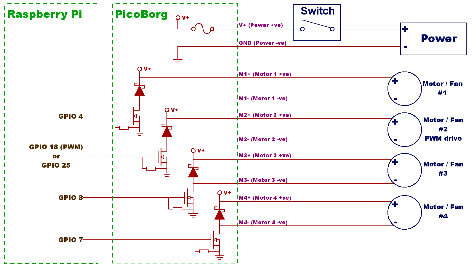
You will want to check that these are all connected:
One connection will be to the V+ hole for +ve, which is one of the red cables on our pre-soldered boards
The other connection will be to the GND hole for -ve, which is the black cable on our pre-soldered boards
On our pre-soledered boards all of the + cables are red
On our pre-soledered boards the various - cables are the other colours of cable
It should be on these pins:
located this way around:
If it still does not work, see this forum post about checking if the fuse is okay:
https://www.piborg.org/comment/818#comment-818
imixman@hotmail.com
Thu, 11/19/2015 - 16:45
Permalink
Okay?
Uh, the GUI doesn't show up when I started it. (the examples GUI)
piborg
Thu, 11/19/2015 - 18:01
Permalink
Problems running PicoBorg scripts
Okay, the first thing to do is see if a simple example works.
Open a terminal and run this command:
sudo ~/picoborg/4dc.pyWhen you see
You can now turn on the power, press ENTER to continuepress ENTERWhen you see
Drives to toggle (Q to quit)?type1234and press ENTERIf the board is working you should now have all four outputs enabled.
If this does not work let us know what happens:
If this script does not work it is unlikely the GUI will work either.
Trying this will hopefully give us a clue as to what the problem is.
imixman@hotmail.com
Thu, 11/19/2015 - 18:11
Permalink
Okay
Alright I got the GUI working anyway, problem is, now, the motors don't move at all. When I ran 4dc.py, I got some warnings once the script started running they are:
4dc.py:15: RuntimeWarning: This channel is already in use, continuing anyway.
Use GPIO.setwarnings(False) to disable warnings.
GPIO.setup(DRIVE_1, GPIO.OUT)
4dc.py:16: RuntimeWarning: This channel is already in use, continuing anyway.
Use GPIO.setwarnings(False) to disable warnings.
GPIO.setup(DRIVE_2, GPIO.OUT)
4dc.py:17: RuntimeWarning: This channel is already in use, continuing anyway.
Use GPIO.setwarnings(False) to disable warnings.
GPIO.setup(DRIVE_3, GPIO.OUT)
4dc.py:18: RuntimeWarning: This channel is already in use, continuing anyway.
Use GPIO.setwarnings(False) to disable warnings.
GPIO.setup(DRIVE_4, GPIO.OUT)
Note: I'm using a RPI B+, I placed my PicoBorg on the first 26 pins.
imixman@hotmail.com
Thu, 11/19/2015 - 18:20
Permalink
nvm
I got rid of the errors, but the motors still don't move an inch.
Again, I'm using a RPI B+, I placed my PicoBorg on the first 26 pins. The script just shows instructions, "ON ON ON ON" after I did "1234" to run the 4 motors.
piborg
Thu, 11/19/2015 - 18:34
Permalink
Connections
Did you check all of the wiring connections as described in one of the previous replies?
Also did you check the fuse?
Pages