
guidence on building my robot/ survival borg
Forums:
Hello,
in short I would like to know how linking 2 ThunderBorg Boards work, apart from giving my 4 motors their own driver(?) is it just a case of allowing separate power also? so I could have 10 aa batteries (advised) on each board? meaning 2 motors have 10 aa batteries each now? meaning twice the life so say? if this is true it leads me to the next part..
so I actually want to use 2 x 8 aa boxes per thunderborg @ 19.2v powering 2 x 12v 450rpm motors will this work ok ?
I also wish to use a power bank for the raspberry pi 4 instead of the aa batteries could any one advise on this I read about leaving the 2 5v jumpers off from pi -th3underborg but daisy chaining to the 2nd board do I do the same 4/6 jumper wires ?
I think lastly the motors say 2kg/cm? I'm trying to work out a good size chassis so I do not have turning issues and the max weight I could carry how could I work this out or any one able to advise?
thanks dr-scape
- Log in to post comments


dr-scape
Thu, 01/30/2020 - 18:20
Permalink
Well nothing popped at me... onwards !
so im now having some trouble with the code I have managed to get both boards set up with ids, 0b11 and 0c12
I have tried adding this
# Board #1, address 11
TB1 = ThunderBorg.ThunderBorg()
TB1.i2cAddress = 11
TB1.Init()
TB1.ResetEpo()
# Board #2, address 12
TB2 = ThunderBorg.ThunderBorg()
TB2.i2cAddress = 12
TB2.Init()
TB2.ResetEpo()
to the # Setup the ThunderBorg lines in the example codes like readbattery.py but nothing works, not even the desktop demo icons. I believe the boards to be connected correctly as the led's show the same patterns on start up and it let me set ids and prints them ., need help please getting a working script going with python so I can then add keyboard functions wasd ect
dr-scape
Thu, 01/30/2020 - 20:38
Permalink
this is the most common error im getting
pygame 1.9.4.post1
Hello from the pygame community. https://www.pygame.org/contribute.html
Loading ThunderBorg on bus 1, address 0B
Found a device at 0B, but it is not a ThunderBorg (ID 15 instead of 0C)
ThunderBorg was not found
Are you sure your ThunderBorg is properly attached, the correct address is used, and the I2C drivers are running?
Loading ThunderBorg on bus 1, address 0C
Found a device at 0C, but it is not a ThunderBorg (ID 15 instead of 0C)
ThunderBorg was not found
Are you sure your ThunderBorg is properly attached, the correct address is used, and the I2C drivers are running?
Scanning I�C bus #1
No ThunderBorg boards found, is bus #1 correct (should be 0 for Rev 1, 1 for Rev 2)
No ThunderBorg found, check you are attached :)
------------------
(program exited with code: 0)
Press return to continue
-----------------------------------------
script trying to use
#!/usr/bin/env python # coding: Latin-1 # Load library functions we want import time import os import sys import pygame import ThunderBorg # Re-direct our output to standard error, we need to ignore standard out to hide some nasty print statements from pygame sys.stdout = sys.stderr # Setup the ThunderBorg TB1 = ThunderBorg.ThunderBorg() TB2 = ThunderBorg.ThunderBorg() TB1.i2cAddress = 11 TB2.i2cAddress = 12 TB1.Init() TB2.Init() if not TB1.foundChip: boards = ThunderBorg.ScanForThunderBorg() if len(boards) == 0: print 'No ThunderBorg found, check you are attached :)' else: print 'No ThunderBorg at address %02X, but we did find boards:' % (TB1.i2cAddress) for board in boards: print ' %02X (%d)' % (board, board) print 'If you need to change the I²C address change the setup line so it is correct, e.g.' print 'TB1.i2cAddress = 0x%02X' % (boards[0]) sys.exit() if not TB2.foundChip: boards = ThunderBorg.ScanForThunderBorg() if len(boards) == 0: print 'No ThunderBorg found, check you are attached :)' else: print 'No ThunderBorg at address %02X, but we did find boards:' % (TB2.i2cAddress) for board in boards: print ' %02X (%d)' % (board, board) print 'If you need to change the I²C address change the setup line so it is correct, e.g.' print 'TB2.i2cAddress = 0x%02X' % (boards[0]) sys.exit() # Ensure the communications failsafe has been enabled! failsafe = False for i in range(5): TB1.SetCommsFailsafe(True) failsafe = TB1.GetCommsFailsafe() if failsafe: break for i in range(5): TB2.SetCommsFailsafe(True) failsafe = TB2.GetCommsFailsafe() if failsafe: break if not failsafe: print 'Board %02X failed to report in failsafe mode!' % (TB1.i2cAddress) sys.exit() if not failsafe: print 'Board %02X failed to report in failsafe mode!' % (TB2.i2cAddress) sys.exit() # Settings for the joystick axisUpDown = 1 # Joystick axis to read for up / down position axisUpDownInverted = False # Set this to True if up and down appear to be swapped axisLeftRight = 2 # Joystick axis to read for left / right position axisLeftRightInverted = False # Set this to True if left and right appear to be swapped buttonSlow = 8 # Joystick button number for driving slowly whilst held (L2) slowFactor = 0.5 # Speed to slow to when the drive slowly button is held, e.g. 0.5 would be half speed buttonFastTurn = 9 # Joystick button number for turning fast (R2) interval = 0.00 # Time between updates in seconds, smaller responds faster but uses more processor time # Power settings voltageIn = 1.2 * 16 # Total battery voltage to the ThunderBorg voltageOut = 12.0 * 0.95 # Maximum motor voltage, we limit it to 95% to allow the RPi to get uninterrupted power # Setup the power limits if voltageOut > voltageIn: maxPower = 1.0 else: maxPower = voltageOut / float(voltageIn) # Show battery monitoring settings battMin, battMax = TB1.GetBatteryMonitoringLimits() battCurrent = TB1.GetBatteryReading() print 'Battery monitoring settings:' print ' Minimum (red) %02.2f V' % (battMin) print ' Half-way (yellow) %02.2f V' % ((battMin + battMax) / 2) print ' Maximum (green) %02.2f V' % (battMax) print print ' Current voltage %02.2f V' % (battCurrent) print battMin, battMax = TB2.GetBatteryMonitoringLimits() battCurrent = TB2.GetBatteryReading() print 'Battery monitoring settings:' print ' Minimum (red) %02.2f V' % (battMin) print ' Half-way (yellow) %02.2f V' % ((battMin + battMax) / 2) print ' Maximum (green) %02.2f V' % (battMax) print print ' Current voltage %02.2f V' % (battCurrent) print # Setup pygame and wait for the joystick to become available TB1.MotorsOff() TB1.SetLedShowBattery(False) TB1.SetLeds(0,0,1) os.environ["SDL_VIDEODRIVER"] = "dummy" # Removes the need to have a GUI window pygame.init() TB2.MotorsOff() TB2.SetLedShowBattery(False) TB2.SetLeds(0,0,1) os.environ["SDL_VIDEODRIVER"] = "dummy" # Removes the need to have a GUI window pygame.init() #pygame.display.set_mode((1,1)) print 'Waiting for joystick... (press CTRL+C to abort)' while True: try: try: pygame.joystick.init() # Attempt to setup the joystick if pygame.joystick.get_count() < 1: # No joystick attached, set LEDs blue TB1.SetLeds(0,0,1) TB2.SetLeds(0,0,1) pygame.joystick.quit() time.sleep(0.1) else: # We have a joystick, attempt to initialise it! joystick = pygame.joystick.Joystick(0) break except pygame.error: # Failed to connect to the joystick, set LEDs blue TB1.SetLeds(0,0,1) TB2.SetLeds(0,0,1) pygame.joystick.quit() time.sleep(0.1) except KeyboardInterrupt: # CTRL+C exit, give up print 'User aborted' TB1.SetCommsFailsafe(False) TB1.SetLeds(0,0,0) sys.exit() TB2.SetCommsFailsafe(False) TB2.SetLeds(0,0,0) sys.exit() print 'Joystick found' joystick.init() TB1.SetLedShowBattery(True) TB2.SetLedShowBattery(True) ledBatteryMode = True try: print 'Press CTRL+C to quit' driveLeft = 0.0 driveRight = 0.0 running = True hadEvent = False upDown = 0.0 leftRight = 0.0 # Loop indefinitely while running: # Get the latest events from the system hadEvent = False events = pygame.event.get() # Handle each event individually for event in events: if event.type == pygame.QUIT: # User exit running = False elif event.type == pygame.JOYBUTTONDOWN: # A button on the joystick just got pushed down hadEvent = True elif event.type == pygame.JOYAXISMOTION: # A joystick has been moved hadEvent = True if hadEvent: # Read axis positions (-1 to +1) if axisUpDownInverted: upDown = -joystick.get_axis(axisUpDown) else: upDown = joystick.get_axis(axisUpDown) if axisLeftRightInverted: leftRight = -joystick.get_axis(axisLeftRight) else: leftRight = joystick.get_axis(axisLeftRight) # Apply steering speeds if not joystick.get_button(buttonFastTurn): leftRight *= 0.5 # Determine the drive power levels driveLeft = -upDown driveRight = -upDown if leftRight < -0.05: # Turning left driveLeft *= 1.0 + (2.0 * leftRight) elif leftRight > 0.05: # Turning right driveRight *= 1.0 - (2.0 * leftRight) # Check for button presses if joystick.get_button(buttonSlow): driveLeft *= slowFactor driveRight *= slowFactor # Set the motors to the new speeds TB1.SetMotor1(driveRight * maxPower) TB1.SetMotor2(driveLeft * maxPower) TB2.SetMotor1(driveRight * maxPower) TB2.SetMotor2(driveLeft * maxPower) # Change LEDs to purple to show motor faults if TB1.GetDriveFault1() or TB1.GetDriveFault2(): if ledBatteryMode: TB1.SetLedShowBattery(False) TB1.SetLeds(1,0,1) ledBatteryMode = False if TB2.GetDriveFault1() or TB2.GetDriveFault2(): if ledBatteryMode: TB2.SetLedShowBattery(False) TB2.SetLeds(1,0,1) ledBatteryMode = False else: if not ledBatteryMode: TB1.SetLedShowBattery(True) ledBatteryMode = True if not ledBatteryMode: TB2.SetLedShowBattery(True) ledBatteryMode = True # Wait for the interval period time.sleep(interval) # Disable all drives TB1.MotorsOff() TB1.MotorsOff() except KeyboardInterrupt: # CTRL+C exit, disable all drives TB1.MotorsOff() TB1.SetCommsFailsafe(False) TB1.SetLedShowBattery(False) TB1.SetLeds(0,0,0) TB2.MotorsOff() TB2.SetCommsFailsafe(False) TB2.SetLedShowBattery(False) TB2.SetLeds(0,0,0) printdr-scape
Thu, 01/30/2020 - 20:41
Permalink
when I change the id's to
when I change the id's to 0B11 and 0C12 I then get this error
File "joy", line 18
TB2.i2cAddress = 0C12
^(under 2 in 12)
SyntaxError: invalid syntax
------------------
(program exited with code: 1)
Press return to continue
any help please
piborg
Fri, 01/31/2020 - 10:36
Permalink
ThunderBorg ID numbers
The ID numbers should either be in decimal:
or in hexadecimal:
Both are actually the same values, so use whichever style you prefer :)
piborg
Fri, 01/31/2020 - 10:33
Permalink
Sounds like the ID in ThunderBorg.py has been altered
It sounds like the ID value in ThunderBorg.py has been altered, ID 15 is correct.
Look for a line starting with
I2C_ID_THUNDERBORGtowards the top of ThunderBorg.py, it should read:If the value is anything else the script will not work correctly.
piborg
Fri, 01/31/2020 - 10:45
Permalink
Powering two ThunderBorgs
You are correct, you can power both ThunderBorgs from separate battery packs. This will extend the running time as each pack only has to drive two motors.
Having two battery packs connected in series per ThunderBorg is also fine to get a higher voltage. You can also remove the 95% maximum limit in the power settings since you are not using the full battery power anyway:
As you do not need the 5V power from the ThunderBorg you can leave the two 5V pins on the ThunderBorgs disconnected from the Raspberry Pi. It does not matter if you connect the ThunderBorgs to each other with just the 4 wires or all 6, it will work either way :)
dr-scape
Fri, 01/31/2020 - 11:49
Permalink
About POWAAAAAA!!!!
im so glad this is how I imagined it, means I should be able to go beast mode.... motors depending..
so I have 2 x 8's 2 live reds 2 ground blacks together into the board is this ok or should I connect like red to black and have 1 red box 1, 1 black box 2 into board :D sorry for bad terminology
as it stands both boards say they have 11-12v going into them witch is abit off the 19.2 it should be?? and im sure they were fully charged can the script make it show less?
as shown below in my joypad script.
Thanks again for any help and advice dr-scape
piborg
Fri, 01/31/2020 - 12:33
Permalink
Connect in series
You should connect one pack's red wire to V+, the other pack's black to GND, and the remaining red and black wires to each other. This is known as connecting in series.
Source: https://tech.txdi.org/seriesandparallel
dr-scape
Fri, 01/31/2020 - 12:54
Permalink
ForWard!
ok so mines not really any of the 2 shown :L on the bottom one the 2 6v packs are both into their respective terminals on the board rather then to the other pack,
im going to change this to the top one and check the readings
Thanks Dr-scape
dr-scape
Fri, 01/31/2020 - 15:55
Permalink
more power then it should O.o
hello done this as stated now they show between 21-22v atm again unsure on battery charge % as I have no way to tell, but they are Duracell 1.2 v 2500 mAh so x 16 is 19.2v unsure why this is slightly over is this to do with the 3.3v in from the pi ??
# Power settings
voltageIn = 19.0 I changed this to 20 .
voltageOut = 12.0 <----
# Setup the power limits ---will these always be 12 maxium because 12v motors?
if voltageOut > voltageIn: ---
maxPower = 12.0 <-------
Thanks for the help and advice, Dr-scape
piborg
Fri, 01/31/2020 - 16:12
Permalink
Battery voltage
This is actually quite normal and nothing to worry about :)
When rechargable AAs are fully charged they will read about 1.3V instead of 1.2V. As they start discharging this quickly falls to around 1.2V and then stays around the same for most of the running time, then drops quickly as they start to get low.
Here are some readings taken from different batteries:
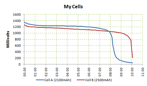
Source: http://adventuresinarduinoland.blogspot.com/2011/02/easy-nimh-discharge-...
You can leave the input voltage as
1.2V × 16 = 19.2Vin the script, it just means your robot will have a slight boost in speed when the batteries are freshly charged (about 8%). This is perfectly fine for the motors.The output voltage should be left at 12V so that the motors are powered at their proper voltage most of the time.
dr-scape
Fri, 01/31/2020 - 18:30
Permalink
Brilliant StuFF
This is great I have left the values as is then how ever what's in the script making the speeds different is the normal forward reverse left right 100% as if u press l2 it slows down all functions by 50% and if you press r2 it speeds up only left and right that's faster then the normal mode speeds, if that makes sense lol so their is a faster option some where?
other then this the proto type version is ready and working happy to say been ripping around the living room for the past few hours winwin battery life is amazing it seems so far
However I will be looking into stronger and lighter batteries in the future to fully meet the 35 v input and saving weight is always good.
im now going to be working on a chassis of a more solid material but have not decided to go 8inch x 8inch or 10inch x 10inch the same as the proto board, and trying to fit this all between the wheel diameter after this I will also test carry weight along with run time, as well as adding some gadgets too
Thanks again for the replies and assistance dr-scape
dr-scape
Fri, 01/31/2020 - 11:40
Permalink
progress made
Hi Piborg thank you very much for the reply's just to be clear on the id's I2C_ID_THUNDERBORG = 0x15 this in the thunderborg pi why is the 15 important? if I changed to 0x0B 11 & 0x0C12 just wondering. O.o
however I got to say with where my journey led me last night I managed to get a few scripts working like battery reader, battery set limits, leds, and am now working on the joystick,
im using a ps4 controller Bluetooth and have managed to edit the script to allow the 2nd thunderborg to work and I have forwards and reverse with left thumb stick up/down however nothing works for left/right and the only other button to work is l2 that turns only 2 motors and then bugs it out to the point I can shimmy the car like a crab …
----------------------------joystickscript-----------------------
#!/usr/bin/env python
# coding: Latin-1

# Load library functions we want
import time
import os
import sys
import pygame
import ThunderBorg

# Re-direct our output to standard error, we need to ignore standard out to hide some nasty print statements from pygame
sys.stdout = sys.stderr

# Setup the ThunderBorg
TB = ThunderBorg.ThunderBorg()  # Create a new ThunderBorg object
TB.i2cAddress = 0x0B           # Uncomment and change the value if you have changed the board address
TB.Init()                       # Set the board up (checks the board is connected)
TB1 = ThunderBorg.ThunderBorg()  # Create a new ThunderBorg object
TB1.i2cAddress = 0x0C           # Uncomment and change the value if you have changed the board address
TB1.Init()                       # Set the board up (checks the board is connected)
if not TB.foundChip:
    boards = ThunderBorg.ScanForThunderBorg()
    if len(boards) == 0:
        print 'No ThunderBorg found, check you are attached :)'
    else:
        print 'No ThunderBorg at address %02X, but we did find boards:' % (TB.i2cAddress)
        for board in boards:
            print '    %02X (%d)' % (board, board)
        print 'If you need to change the I²C address change the setup line so it is correct, e.g.'
        print 'TB.i2cAddress = 0x%02X' % (boards[0])
    sys.exit()

if not TB1.foundChip:
    boards = ThunderBorg.ScanForThunderBorg()
    if len(boards) == 0:
        print 'No ThunderBorg found, check you are attached :)'
    else:
        print 'No ThunderBorg at address %02X, but we did find boards:' % (TB1.i2cAddress)
        for board in boards:
            print '    %02X (%d)' % (board, board)
        print 'If you need to change the I²C address change the setup line so it is correct, e.g.'
        print 'TB1.i2cAddress = 0x%02X' % (boards[0])
    sys.exit()

# Ensure the communications failsafe has been enabled!
failsafe = False
for i in range(5):
    TB.SetCommsFailsafe(True)
    failsafe = TB.GetCommsFailsafe()
    if failsafe:
        break
if not failsafe:
    print 'Board %02X failed to report in failsafe mode!' % (TB.i2cAddress)
    sys.exit()

failsafe = False
for i in range(5):
    TB1.SetCommsFailsafe(True)
    failsafe = TB1.GetCommsFailsafe()
    if failsafe:
        break
if not failsafe:
    print 'Board1 %02X failed to report in failsafe mode!' % (TB1.i2cAddress)
    sys.exit()

# Settings for the joystick
axisUpDown = 1                          # Joystick axis to read for up / down position
axisUpDownInverted = True              # Set this to True if up and down appear to be swapped
axisLeftRight = 2                       # Joystick axis to read for left / right position
axisLeftRightInverted = True           # Set this to True if left and right appear to be swapped
buttonSlow = 8                          # Joystick button number for driving slowly whilst held (L2)
slowFactor = 0.5                        # Speed to slow to when the drive slowly button is held, e.g. 0.5 would be half speed
buttonFastTurn = 9                      # Joystick button number for turning fast (R2)
interval = 0.00                         # Time between updates in seconds, smaller responds faster but uses more processor time

# Power settings
voltageIn = 19.0                        # Total battery voltage to the ThunderBorg
voltageOut = 12.0                       # Maximum motor voltage

# Setup the power limits
if voltageOut > voltageIn:
    maxPower = 12.0
else:
    maxPower = voltageOut / float(voltageIn)

# Show battery monitoring settings
battMin, battMax = TB.GetBatteryMonitoringLimits()
battCurrent = TB.GetBatteryReading()
print 'Battery monitoring settings:'
print '    Minimum  (red)     %02.2f V' % (battMin)
print '    Half-way (yellow)  %02.2f V' % ((battMin + battMax) / 2)
print '    Maximum  (green)   %02.2f V' % (battMax)
print
print '    Current voltage    %02.2f V' % (battCurrent)
print
battMin, battMax = TB1.GetBatteryMonitoringLimits()
battCurrent = TB1.GetBatteryReading()
print 'Battery monitoring1 settings:'
print '    Minimum  (red)     %02.2f V' % (battMin)
print '    Half-way (yellow)  %02.2f V' % ((battMin + battMax) / 2)
print '    Maximum  (green)   %02.2f V' % (battMax)
print
print '    Current voltage    %02.2f V' % (battCurrent)
print

# Setup pygame and wait for the joystick to become available
TB.MotorsOff()
TB.SetLedShowBattery(False)
TB.SetLeds(0,0,1)
os.environ["SDL_VIDEODRIVER"] = "dummy" # Removes the need to have a GUI window
pygame.init()
TB1.MotorsOff()
TB1.SetLedShowBattery(False)
TB1.SetLeds(0,0,1)
os.environ["SDL_VIDEODRIVER"] = "dummy" # Removes the need to have a GUI window
pygame.init()
#pygame.display.set_mode((1,1))
print 'Waiting for joystick... (press CTRL+C to abort)'
while True:
    try:
        try:
            pygame.joystick.init()
            # Attempt to setup the joystick
            if pygame.joystick.get_count() < 1:
                # No joystick attached, set LEDs blue
                TB.SetLeds(0,0,1)
                pygame.joystick.quit()
                time.sleep(0.1)
                TB1.SetLeds(0,0,1)
                pygame.joystick.quit()
                time.sleep(0.1)
            else:
                # We have a joystick, attempt to initialise it!
                joystick = pygame.joystick.Joystick(0)
                break
        except pygame.error:
            # Failed to connect to the joystick, set LEDs blue
            TB.SetLeds(0,0,1)
            pygame.joystick.quit()
            time.sleep(0.1)
            TB1.SetLeds(0,0,1)
            pygame.joystick.quit()
            time.sleep(0.1)
    except KeyboardInterrupt:
        # CTRL+C exit, give up
        print '\nUser aborted'
        TB.SetCommsFailsafe(False)
        TB.SetLeds(0,0,0)
        sys.exit()
        TB1.SetCommsFailsafe(False)
        TB1.SetLeds(0,0,0)
        sys.exit()
print 'Joystick found'
joystick.init()
TB.SetLedShowBattery(True)
TB1.SetLedShowBattery(True)
ledBatteryMode = True
try:
    print 'Press CTRL+C to quit'
    driveLeft = 0.0
    driveRight = 0.0
    running = True
    hadEvent = False
    upDown = 0.0
    leftRight = 0.0
    # Loop indefinitely
    while running:
        # Get the latest events from the system
        hadEvent = False
        events = pygame.event.get()
        # Handle each event individually
        for event in events:
            if event.type == pygame.QUIT:
                # User exit
                running = False
            elif event.type == pygame.JOYBUTTONDOWN:
                # A button on the joystick just got pushed down
                hadEvent = True
            elif event.type == pygame.JOYAXISMOTION:
                # A joystick has been moved
                hadEvent = True
            if hadEvent:
                # Read axis positions (-1 to +1)
                if axisUpDownInverted:
                    upDown = -joystick.get_axis(axisUpDown)
                else:
                    upDown = joystick.get_axis(axisUpDown)
                if axisLeftRightInverted:
                    leftRight = -joystick.get_axis(axisLeftRight)
                else:
                    leftRight = joystick.get_axis(axisLeftRight)
                # Apply steering speeds
                if not joystick.get_button(buttonFastTurn):
                    leftRight *= 1.5
                # Determine the drive power levels
                driveLeft = -upDown
                driveRight = -upDown
                if leftRight < -1.05:
                    # Turning left
                    driveLeft *= 2.0 + (4.0 * leftRight)
                elif leftRight > 1.05:
                    # Turning right
                    driveRight *= 2.0 - (4.0 * leftRight)
                # Check for button presses
                if joystick.get_button(buttonSlow):
                    driveLeft *= slowFactor
                    driveRight *= slowFactor
                # Set the motors to the new speeds
                TB.SetMotor1(driveRight * maxPower)
                TB.SetMotor2(driveLeft * maxPower)
                TB1.SetMotor1(driveRight * maxPower)
                TB1.SetMotor2(driveLeft * maxPower)
        # Change LEDs to purple to show motor faults
        if TB.GetDriveFault1() or TB.GetDriveFault2():
            if ledBatteryMode:
                TB.SetLedShowBattery(False)
                TB.SetLeds(1,0,1)
                ledBatteryMode = False
        else:
            if not ledBatteryMode:
                TB.SetLedShowBattery(True)
                ledBatteryMode = True
        # Wait for the interval period
        time.sleep(interval)
    # Disable all drives
    TB.MotorsOff()
    TB1.MotorsOff()
except KeyboardInterrupt:
    # CTRL+C exit, disable all drives
    TB.MotorsOff()
    TB.SetCommsFailsafe(False)
    TB.SetLedShowBattery(False)
    TB.SetLeds(0,0,0)
    TB1.MotorsOff()
    TB1.SetCommsFailsafe(False)
    TB1.SetLedShowBattery(False)
    TB1.SetLeds(0,0,0)
print
---------------------------END--------------------------
thanks again for any help or advise Dr-scape
piborg
Fri, 01/31/2020 - 12:44
Permalink
The 0x15 ID number is used by
The
0x15ID number is used by the script to check the board it is talking to is actually a ThunderBorg. The script sends the board a message asking for its type number and all ThunderBorgs will respond with0x15. This is helpful when you have different types of board connected to check it is talking to the right one :)I think the joystick settings in the example are setup for a PS3 controller from memory. Try these settings instead:
dr-scape
Fri, 01/31/2020 - 12:50
Permalink
hahaha the smile :D
Well done piborg well done this worked!
Thanks Dr-scape
dr-scape
Fri, 01/31/2020 - 16:09
Permalink
Next More Robotie/survival
so to start small how do I add code into my scripts like the joypad to add function for led, buzzer, sensors ect
for example lazer pointer sensor to pin 38 , and a free ground pin, and probably to turn on and off with a button press,
next I see a lot about adding gps for many benefits how do you go about this I have a mini hub with sim that can plug usb to the pi giving me the internet and services or a old phone usb teather will any of these work as ive heard of people doing it with a usb dongle n sim, or do I have to buy some type of gps hat for the pi,
once I have this either way how do you go about adding these functions into the script maybe start small and get it to under stand the boundary it lives in also dose this even need gps or just a pi cam ?
Thanks again Dr-scape
dr-scape
Sat, 02/01/2020 - 20:38
Permalink
keyboard ? function
hi
how do I simple add w a s d function to the joypad.py so I can fully go to my hearts content with out range issues,
thanks dr-scape
piborg
Sun, 02/02/2020 - 09:55
Permalink
You can use the pygame.key
You can use the
pygame.keymodule to look for keyboard input.These pages explain how it works:
https://nerdparadise.com/programming/pygame/part6
https://stackoverflow.com/questions/16044229/how-to-get-keyboard-input-i...
Here is the full documentation:
https://www.pygame.org/docs/ref/key.html
dr-scape
Sun, 02/02/2020 - 10:39
Permalink
Thank You
thanks piborg, really great help for me will work on this, should have it done by later, im having issues when trying to use any pi cam scripts always error on line import cv2, i guess i have not set this up properly?
to be clear my borg has its own 4g internet connected via cloud to vnc phone or pc why i need the w a s d to remove the Bluetooth range for controls(note: i did try the ps4 Bluetooth to phone but it doesn't seem to relay to the pi ) , with that im still desperately trying to find a reasonable sized chassis at 10 w x10 L inch i find the wheels are to close to handle going up some stuff so would a slight longer wheel base help like 10Wx 12L inch optional also reducing the W to 8 inch so 8Wx 12L inch. Thanks again you have been a massive help. i will upload pics soon of the project. dr-scape
piborg
Mon, 02/03/2020 - 09:47
Permalink
OpenCV
You probably need to install OpenCV. Try this command:
If that does not fix it take a copy / screenshot of the error and I will take a look :)
dr-scape
Mon, 02/03/2020 - 23:41
Permalink
hello thank you this did seem
hello thank you this did seem to fix the import error were a few libraries missing, I ran into different errors now for different scripts ill get screen shots of these asap,
the ballfollow.pw from diddy borg dose it need a photo of a red ball I have to work and if so where do I place it so it will be found? because I feel this might be the error it was on about :)
I have another question if I kept the same build but swapped 2 x thunderborgs for diablos will this mean my car will go faster as its 55a per motor then 5a? and how do I know if each motor is getting 12v 5a ? and then I would like to know if a kit like this would be able to be built https://www.amazon.co.uk/JMT-Combo-Set-250-Drone/dp/B07SK8CDJT/ref=sr_1_... using similar set up for a quad/oct drone (I did notice in this kit it asks for 16a so would this rule out thunderborgs and would a diablo be too strong? )
Thank you for help dr-scape
dr-scape
Tue, 02/04/2020 - 13:22
Permalink
code smoke..!!!
Hi piborg today I have ran into error I swapped chassis over today going slightly bigger but once I finished the rebuild and booted up the joystick py smoke started to pour out the borg, killing all power, and inspecting the ground wire from the pi 4, to borg board 1 has evaporated I do know the pi still works but have not tried to re wire the borgs yet as looking for advice ive never noticed a issue and have pictures/steps of my build so I followed the same wires ect, on the rebuild, I did have to change the jumper wire as the pin snapped on the original after removal, but would not see why this would make it burn, and would this have likely destroyed the borg borads ? O.o
thanks dr-scape
piborg
Tue, 02/04/2020 - 19:05
Permalink
Terrible news :(
That is terrible news :(
Generally speaking there are two main causes of these problems:
Is your chassis metal? If it is then you may have a short circuit between the bottom of one of the boards and the chassis.
I would suggest taking some pictures of the top and bottom of both ThunderBorgs so we can see if there is any visible damage. They might be okay, or they may be damaged.
It would also be a good idea to check the batteries are okay. If there is any sign of melting, leaking, or bulging you should dispose of them and get new ones. Damaged batteries can be dangerous.
dr-scape
Tue, 02/04/2020 - 19:35
Permalink
yeh a sad day indeed...
so ive gathered as much as I can and just bad let me know what u think (part1)
dr-scape
Tue, 02/04/2020 - 19:53
Permalink
part 2
...
dr-scape
Wed, 02/05/2020 - 12:09
Permalink
i'd say its broken ..
i'm baffled at this from going from my kitchen side to living room floor for test driving done nothing else the kits been the same all week the only thing changed today was the chassis size, (and jumper wires that needed replacing) all made of wood /plastic screws and fixtures any showing metal like on /off switch terminals i either electric taped or hot glued to seal,
so just the 2 thunderborgs broke i tried them stand alone with no motors and the led blinks once either red or purple turning the power supply off only, motors, batteries, raspberry pi, all seem good and working I tested it using a sb components motor shield however it cant fully handle the motors but they moved , so what went wrong here, the one borg that tiny silver thing was off when it came and i hot glued it back in place and had the borg working so unsure if to do with this or again the wire itself
thanks dr-scape
piborg
Fri, 02/07/2020 - 12:57
Permalink
Badly damaged
That looks like at least one of the boards has been badly damaged, best guess things got rather hot!
I can only suspect that something has caused one of the power connection (battery, 5V or 3.3V) to get connected to ground. Unfortunately with that much damage it may be impossible to tell what the cause was by looking at the boards.
The state of that wire suggests things did get very hot, I would highly recommend checking the batteries carefully for any signs of damage, however small.
It is possible that the broken off capacitor was not really doing its job after you re-attached it due to poor contact with the board electrically. One thought is that power spike from one of the motors caused the problem (that is what they are there to prevent), causing damage to one of the ThunderBorgs, which then caused the full problem - this is just a guess though.
Looking at the last photo, there appears to be damage to the main logic chip on that board. Given the overall state of that board I think it suffered most of the damage and would not be worth trying to repair.
With only V+ and GND connected to a battery (no connection to a Pi or anything else) the LED should not come on at all. If it does it would suggest that the 3.3V line is connected to 5V somewhere on the board.