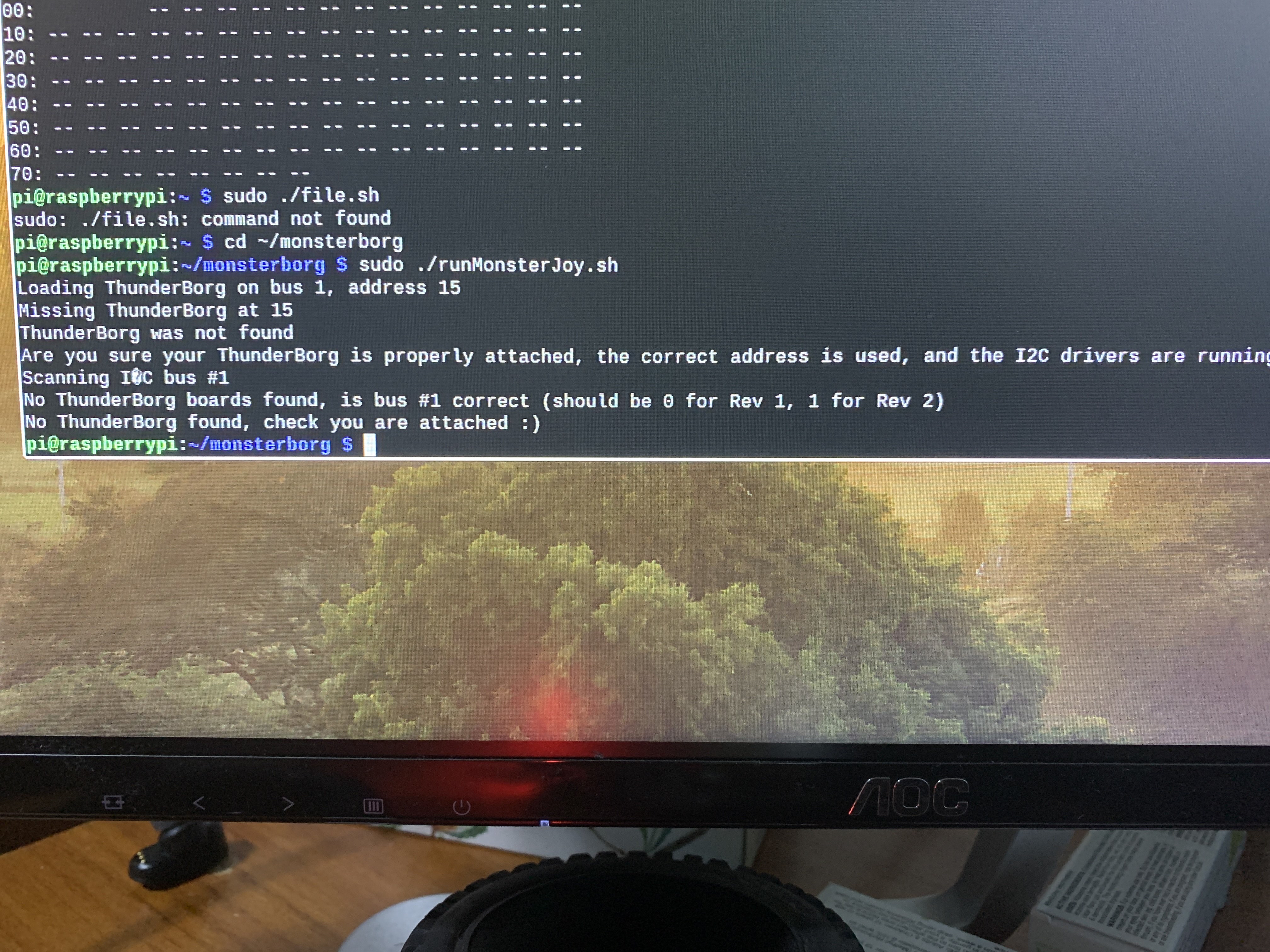
Loading ThunderBorg on bus 1, address 15 Missing Thunderbord 15
Forums:
i currently trying to get the demo monster joy code working with a ps3 controller that is already bluetooth connected.
Images:
- Log in to post comments

i currently trying to get the demo monster joy code working with a ps3 controller that is already bluetooth connected.


piborg
Wed, 08/18/2021 - 13:26
Permalink
No ThunderBorg found
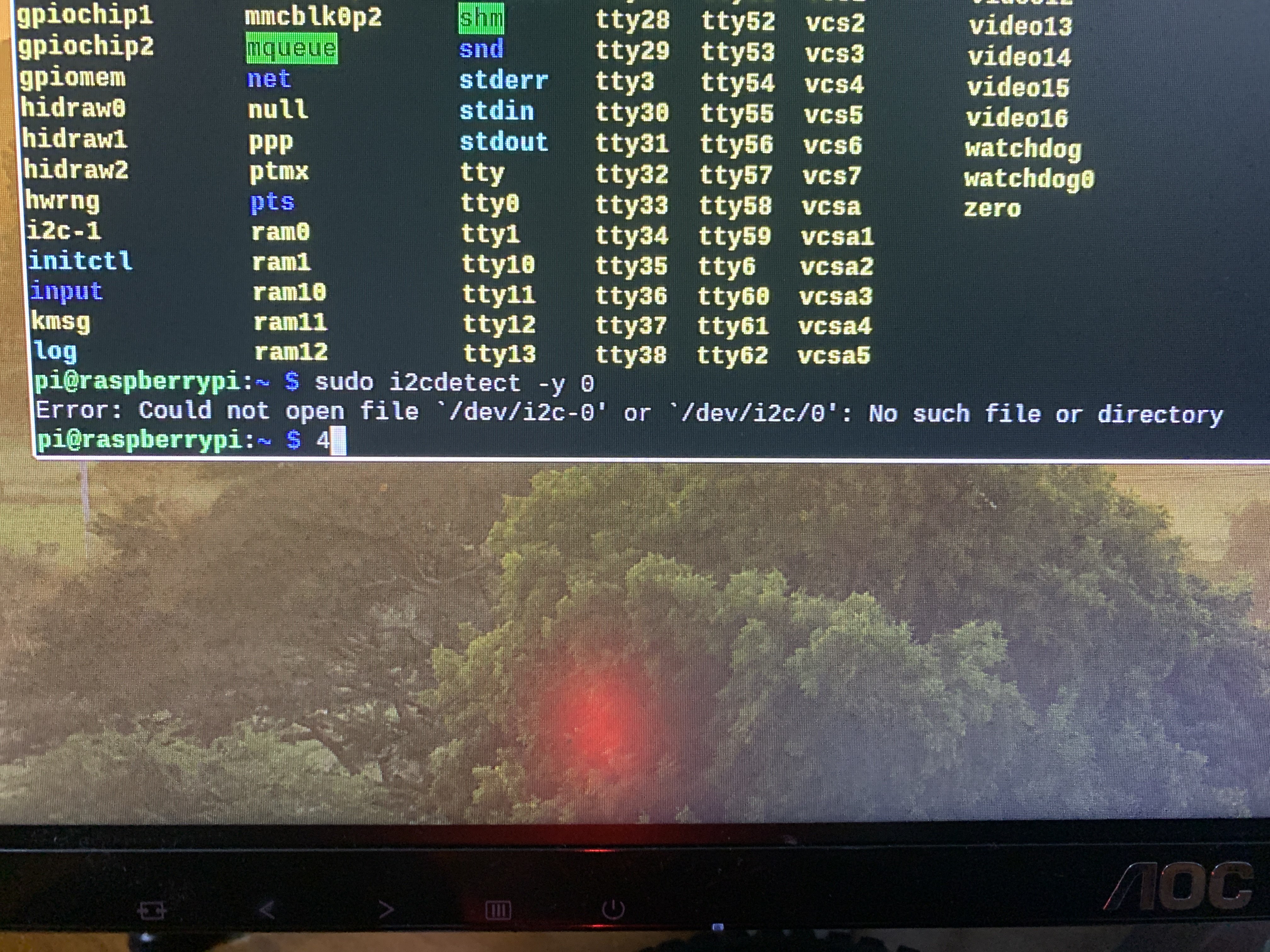
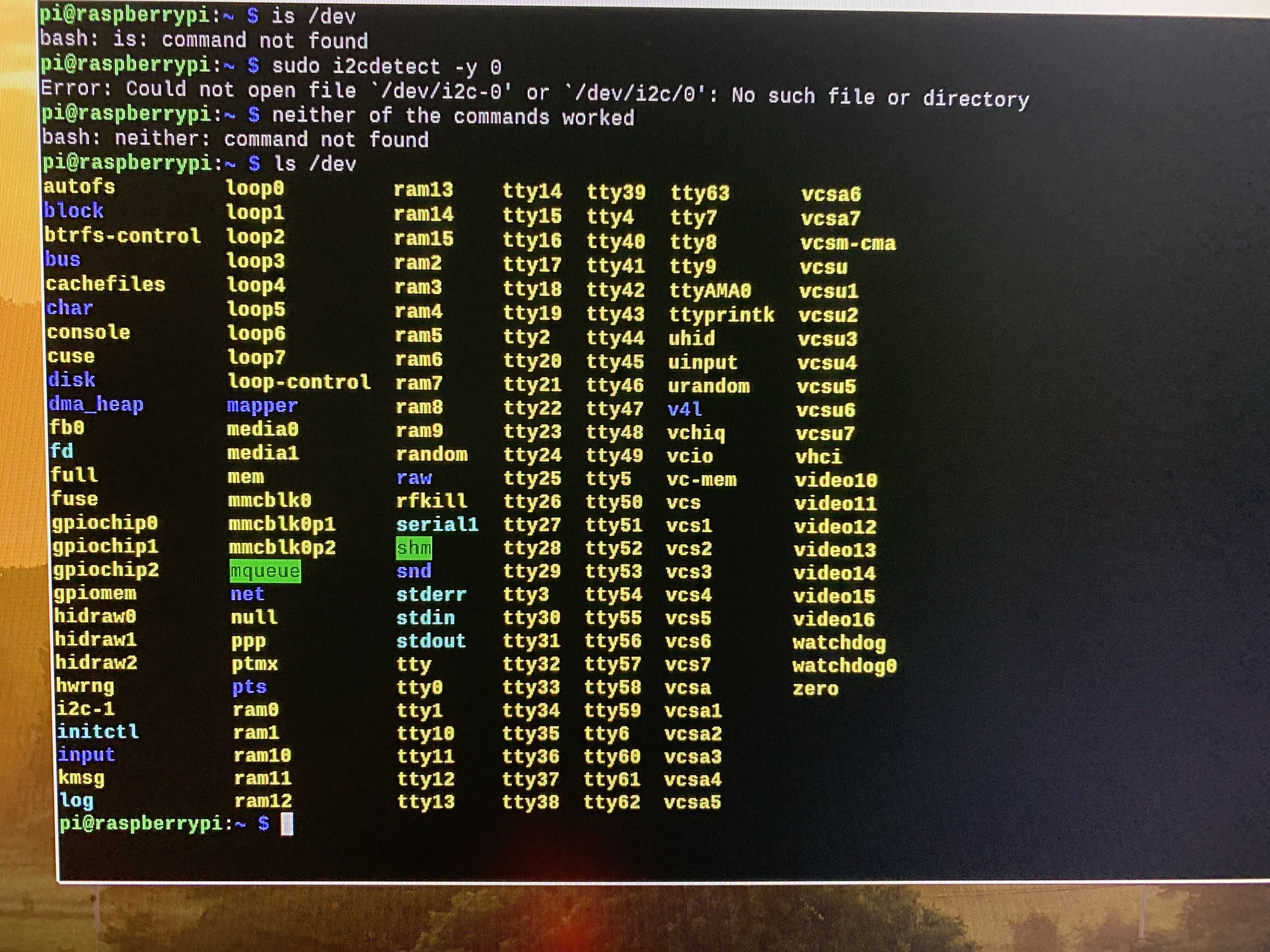
The problem is that the Raspberry Pi is unable to communicate with the ThunderBorg at all, shown by the empty result you received from the
sudo i2cdetect -y 1command.Usually this would mean there is a problem with the wires connecting the Raspberry Pi to the ThunderBorg. Since you appear to have a MonsterBorg kit the connection is plugged in directly so there are no cables.
Unfortunately this means that there is a problem with with the ThunderBorg or the Raspberry Pi preventing communication.
When you turn the power on what sequence of colours does the LED on the ThunderBorg show?
CougarTG
Wed, 08/18/2021 - 15:51
Permalink
light colours when turned on
Red green blue then solid red
btw the kit is indeed a monsterborg kit
piborg
Wed, 08/18/2021 - 16:40
Permalink
Testing the Pi's I2C pins
That is the sequence you should see, so the ThunderBorg's onboard logic is running correctly.
The most likely explanation is that the I2C pins on one of the boards are faulty. You can test the I2C pins on the Raspberry Pi to see if they are okay. If the Pi's pins are faulty then it is the problem, if not then the ThunderBorg is faulty.
Unfortunately you will need to disconnect the ThunderBorg from the Raspberry Pi in order to test the I2C pins on the Pi - the test needs the GPIO header to not be connected to anything in order to work.
Once you have disassembled the MonsterBorg enough to remove the Pi you can test the I2C pins.
Download and build the WiringPi code:
After it has built run the GPIO pin tester:
You should see some diagnostics after pressing ENTER:
PinTest
=======

This is a simple utility to test the GPIO pins on your Raspberry Pi.

NOTE: All GPIO peripherals must be removed to perform this test. This
  includes serial, I2C and SPI connections. You may get incorrect results
  if something is connected and it interferes with the test.

This test can only test the input side of things. It uses the internal
pull-up and pull-down resistors to simulate inputs. It does not test
the output drivers.

You will need to reboot your Pi after this test if you wish to use the
serial port as it will be left in GPIO mode rather than serial mode.

This test only tests the original pins present on the Rev A and B. It
does not test the extra pins on the Revision A2, B2 nor the A+ or B+

Please make sure everything is removed and press the ENTER key to continue,
or Control-C to abort...

          The main 8 GPIO pins  0: 7:  OK
                The 5 SPI pins 10:14:  OK
               The serial pins 15:16:  OK
                  The I2C pins  8: 9:  OK
Hopefully all of the end lines say
OK, indicating that the Raspberry Pi's GPIO pins are fine and that the problem is with the ThunderBorg.If you see faults then the GPIO on the Raspberry Pi is not working correctly and is probably causing the problem. In this case the Pi itself will need to be replaced.
After the test restart the Raspberry Pi to reset the GPIO pins back to their standard behaviour.
CougarTG
Thu, 08/19/2021 - 02:55
Permalink
i couldn't get the code to work
the code says no directory i copy pasted the code
piborg
Thu, 08/19/2021 - 08:56
Permalink
Sorry, wrong case :)
Sorry about the typo, it should be
cd WiringPiwith the first letter as uppercase :)I have corrected the instructions above.
CougarTG
Thu, 08/19/2021 - 11:47
Permalink
Permission denied
i tried the new code but i got a permission denied line
piborg
Thu, 08/19/2021 - 12:36
Permalink
Permission denied
That's unusual. Try running the same command using
sudolike this:CougarTG
Thu, 08/19/2021 - 15:39
Permalink
command not found
said command was not found copy pasted your code
piborg
Thu, 08/19/2021 - 17:11
Permalink
I just tried the sequence
I just tried the sequence myself, it seems that the pintest script no longer gets set to be executable like it used to :(
Run this command to make the script executable first:
Then you should be able to run it normally:
I will update the instructions in the earlier post to include the extra step :)
CougarTG
Tue, 08/24/2021 - 07:37
Permalink
What dose this mean>>
The code worked but I'm not sure what it means
piborg
Tue, 08/24/2021 - 18:02
Permalink
Unexpected result
Well that is not a result I was expecting at all...
Based on the top section it seems like the I2C on the Raspberry Pi is probably okay since both pins passed checks. This would suggest the problem is with the ThunderBorg.
The second section shows that it is detecting some faults on the GPIO header. Each pin has been read and the values (V) either read back with a 1 for high or a 0 for low.
The only pins with should read a 1 / high are the SDA and SCL pins, of which there are four. These all appear fine.
All of the other pins read should have come back with 0 / low. Most of them have, but some have read a 1 instead. For example GPIO.25 (towards the bottom left) read back 1 instead of 0. This indicates that the Raspberry Pi is having some issues with the GPIO.
So in summary the Pi does have some GPIO faults, but as far as the test can determine the I2C pins are fine. I suspect this means the ThunderBorg is the problem, however it is possible the Pi is faulty and the test cannot detect it.
I know this is a long-shot, but do you by any chance have another Raspberry Pi that you can try this same pin test on?
CougarTG
Wed, 08/25/2021 - 01:35
Permalink
Unexpected result
no i do not have another raspberry pi this was my only one any suggestions on what i should do next???
piborg
Wed, 08/25/2021 - 09:50
Permalink
Replacement board
No worries, it was just something we could try before replacing items.
From what we can tell based on the GPIO testing it is most likely the ThunderBorg itself that is at fault.
If you could send a message using our contact form we will arrange to get a replacement board shipped out to you. Select the "Direct contact" category and include the shipping address for the replacement.