
DiddyBorg Metal Edition
Please note these instructions are also available as a pdf download from Instructables.com
Once built, it is near impossible to access the HDMI slot, power slot etc. It is recommended to set up the software first, such as the Raspberry Pi camera, software for any Wifi or bluetooth dongle you might want to use and anything you might need/want to run such as PicoBorg Reverse software and any DiddyBorg scripts. A small guide is here which will get you going with some example scripts.
Building DiddyBorg Metal Edition is very similar to building DiddyBorg Classic, so we will use images interchangeably. Where there is a difference, it is noted and different images are used.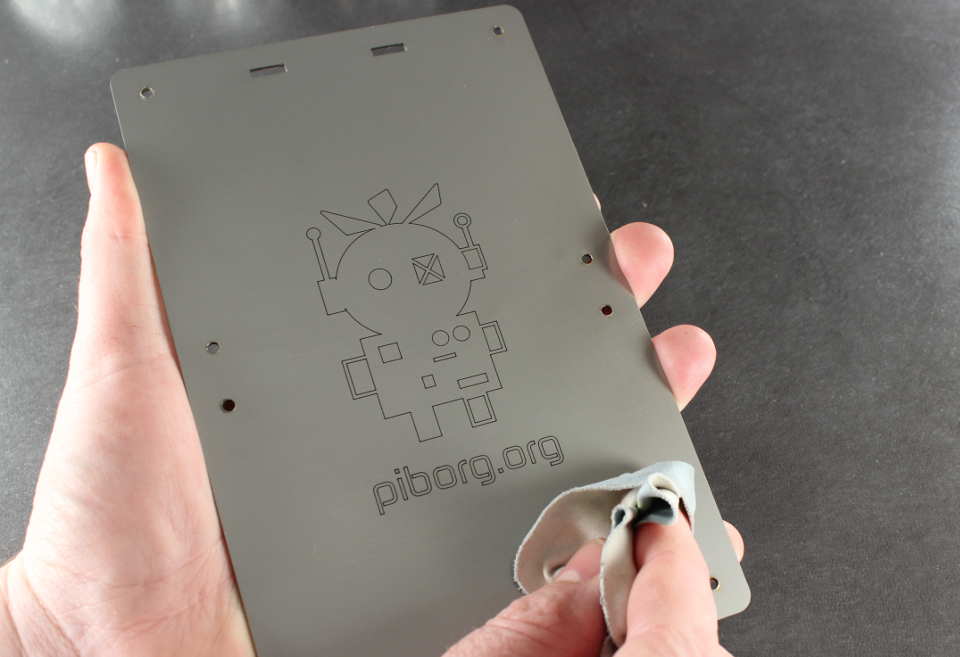
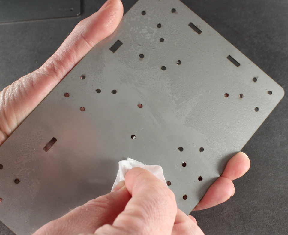
The Stainless Steel top and bottom are laser cut, and are covered with a protective oil, which you can remove with IPA or stainless cleaner. The Kit includes a small towell which is ideal for wiping the steel clean.
You will need to place 4x[M3x12 Cheese screw]s and 4x[M3 Spring washer]s into a motor mount. Make sure the orientation of the motor mount is as per the picture. *Please note the [M3x12 Cheese screw]s are different from the [M3x8 Cheese screw]s
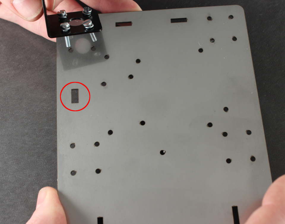
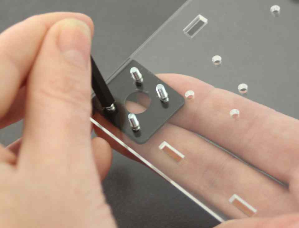
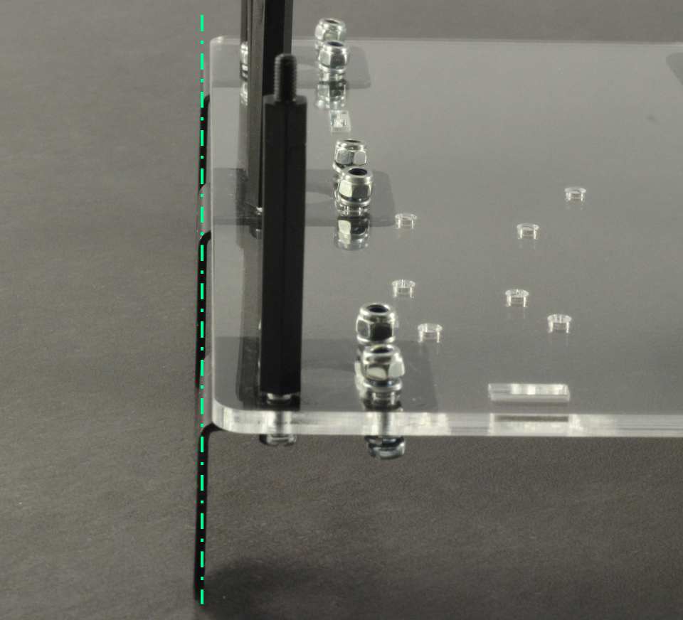
Take the base board and orient it so that the short thick rectangular cut out is at the top left, as in the picture. Place the motor mount on top, with the rounded edge facing up, and locate the four screws in the holes of the steel.
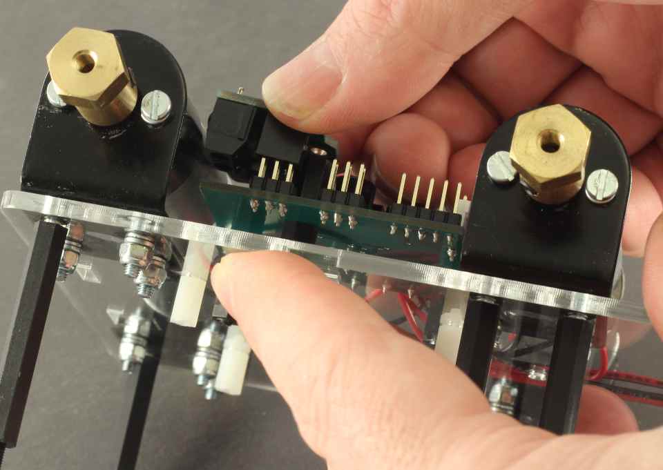
Hold the screws in with your finger tips, and turn the board around
Place a [M3x40 Brass post] on the screw which is closest to the corner of the Steel Plate. Tighten this gently with your fingers. We will tighten this correctly later.
*Please note there is no spring washer on this side
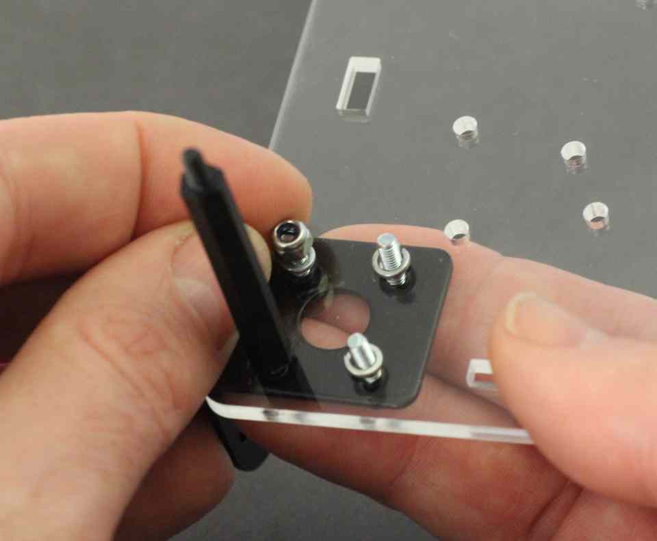
Place 3x[M3 Spring washer]s and 3x[M3 Lock nut]s on the remaining holes, and tighten gently with your fingers.
Do the same for the middle motor mount, with the exception that there are two [M3x40 Brass post]s, on the two holes towards the outside edge of the Steel Plate. Again, the posts have a spring washer only on one side.
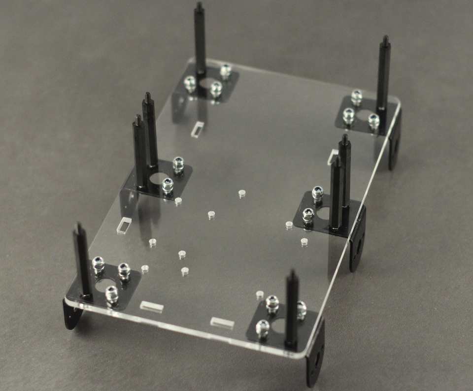
Repeat above for remaining four motor mounts as per image.
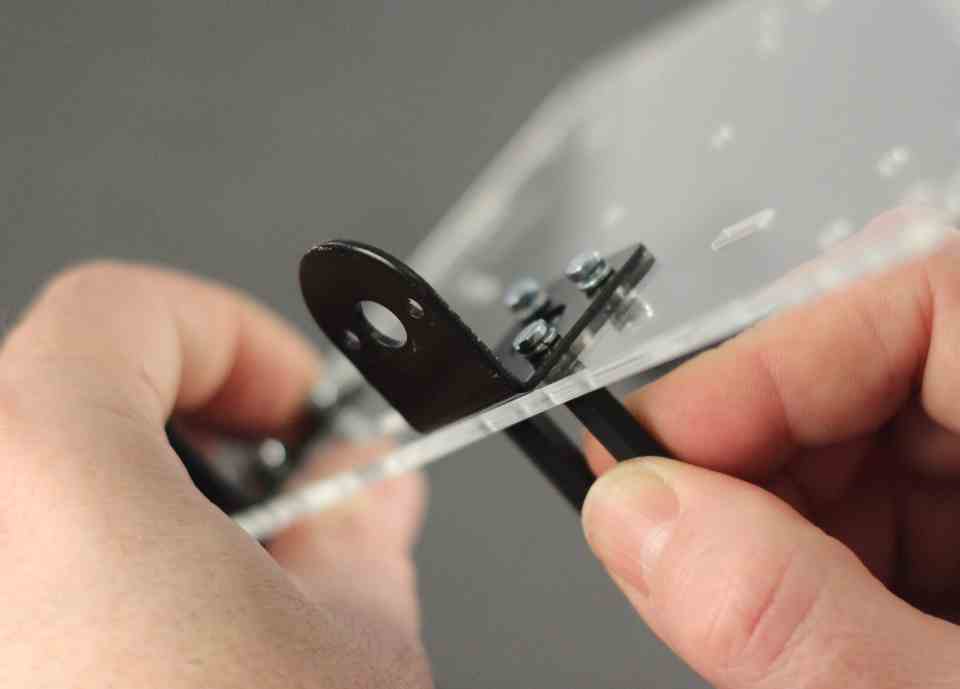
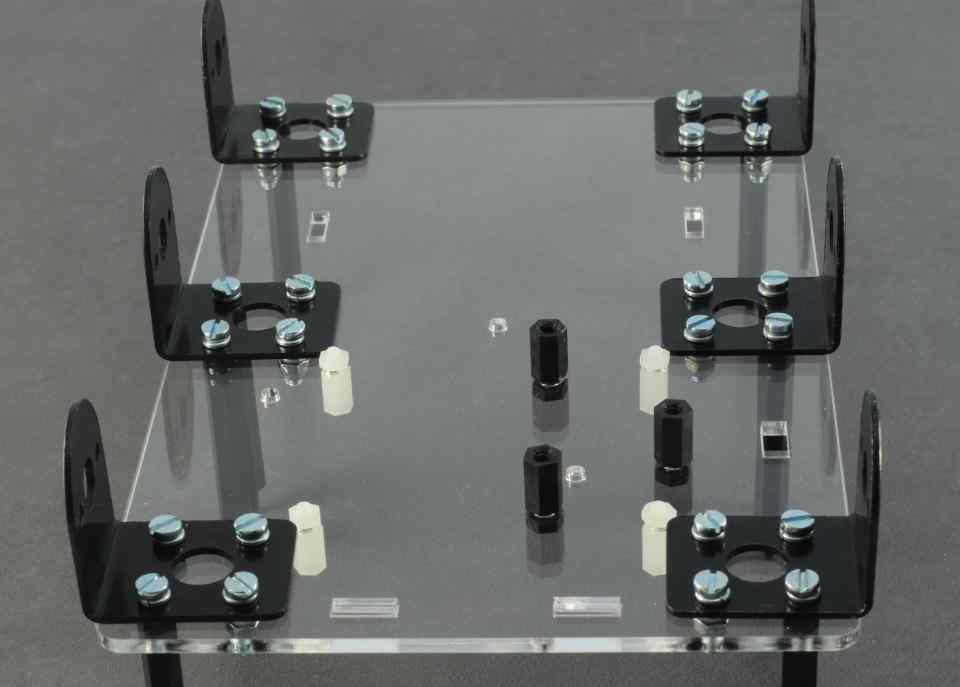
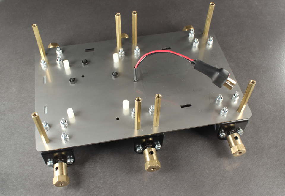
Position the mounts so that they are aligned - that is, they should be level on the same plane. The image highlights this. Once the alignment is correct, tighten the Brass posts gently by hand. Do not overtighten, or you could strip the thread from the Brass post. We just need to tighten to the point where we have crushed the spring washer underneath so it is flat.
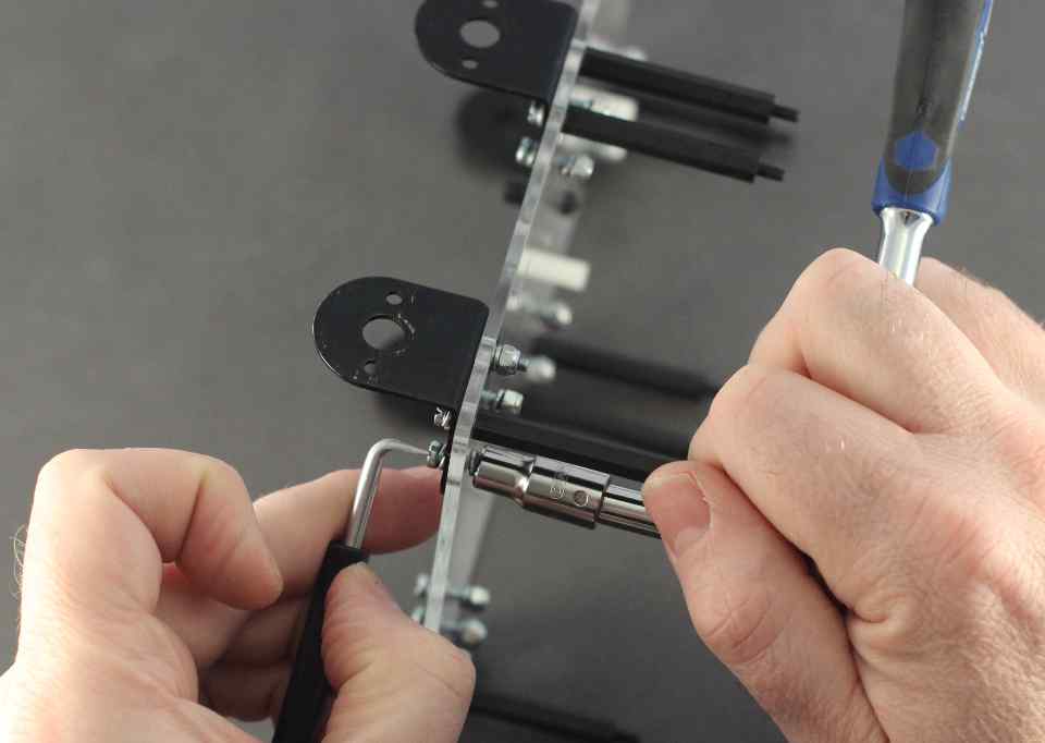
Tighten the screws using a flat bladed screw driver and a 5.5mm socket or spanner. Do not overtighten. Again, tighten just to the point where the spring washers are flat. This is a particularly fiddly part of the assembly, so you might need a third hand!
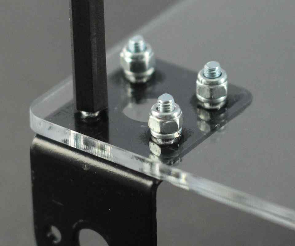
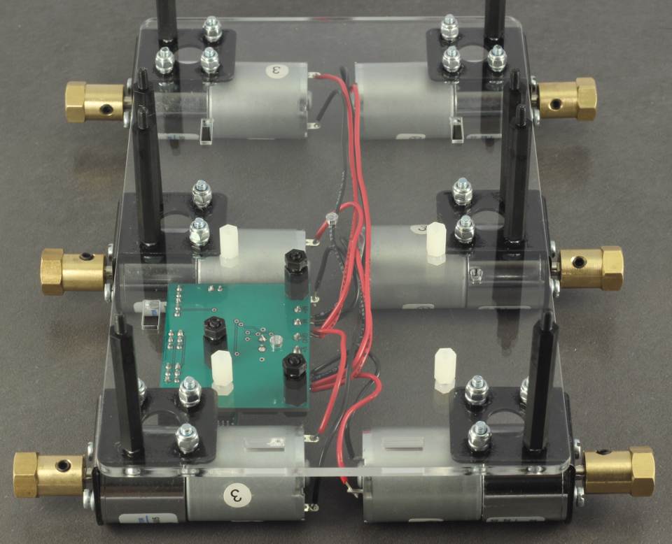
Orient the board so it has the posts facing up. This image also shows the spring washers correctly crushed.
Place the 3x[M3x10 black post]s in the holes as shown in the image. They should be oriented so the post is facing downwards. Add and gently tighten the 3x[M3 Black Nylon nut]s on top.
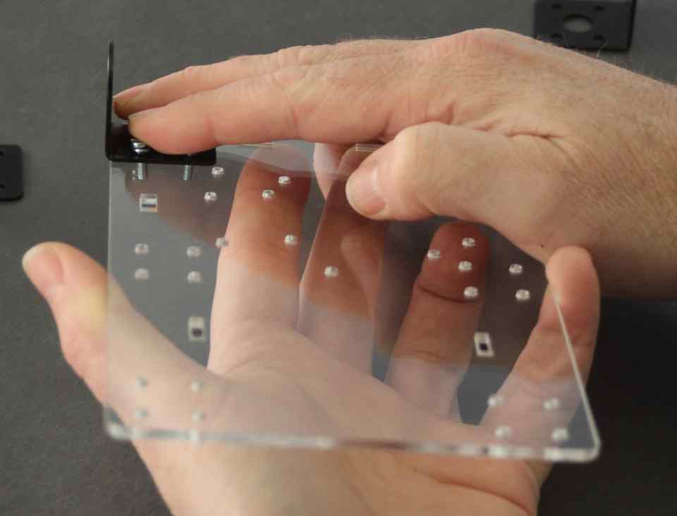
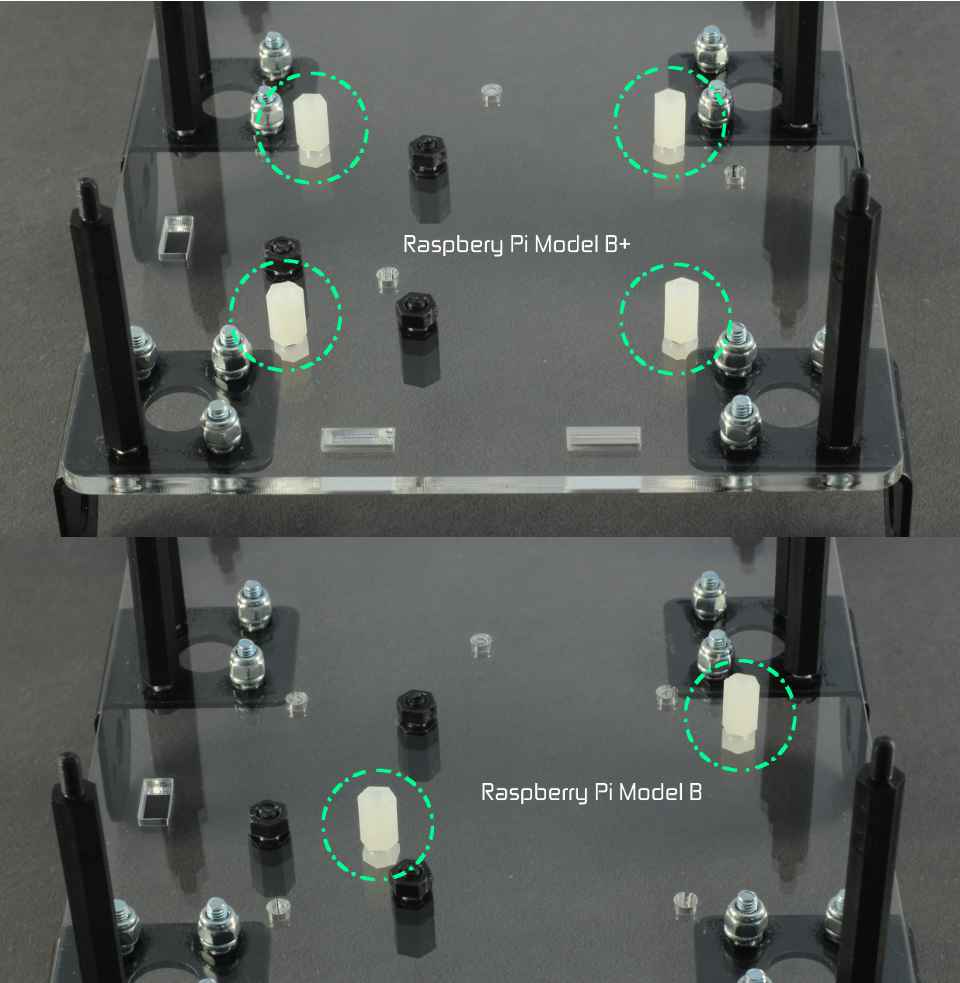
If you have a Raspberry Pi model B+, place the 4x [M2.5x10 white post]s in the four holes as shown in the top diagram. Add the 4x [M2.5 Nut]s. If you have a model B, place 2x of the [M2.5x10 white post]s in the two holes shown in the bottom diagram. Add the 2x [M2.5 Nut]s.
Orient the board so that the long posts are facing down.
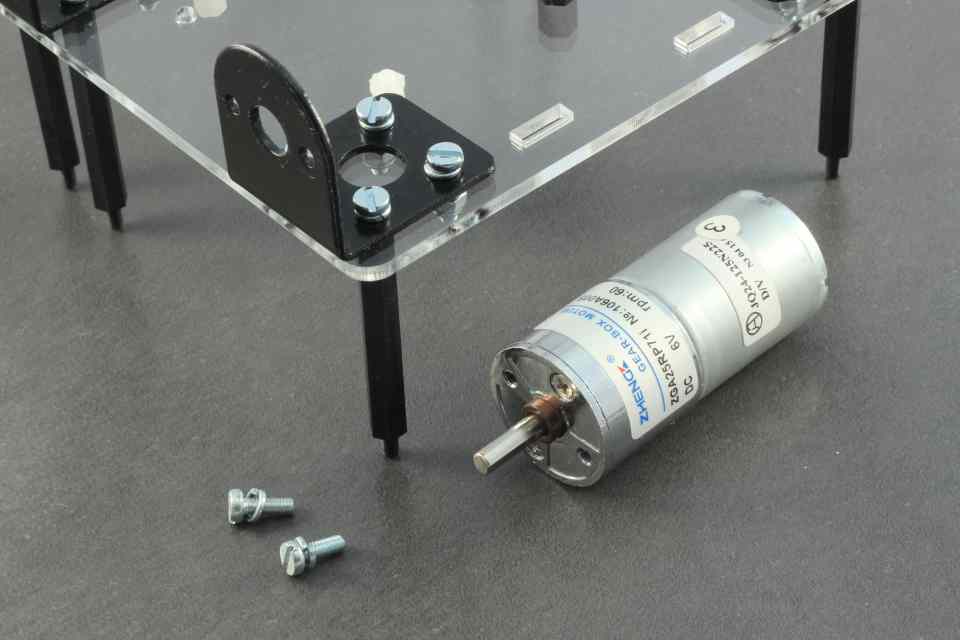
Take 2x[M3x8 Cheese screw]s, add 2x[M3 Spring washer]s to the screws. Place a motor in the mount, and align the motor holes with the mount. Insert and moderately tighten the screws until the washers have collapsed well.
*Note the motors are in the same orientation - that is, with the stickers facing up. This keeps the polarity of the motor connections consistent which will be helpful soon.
Repeat for all 6 motors.
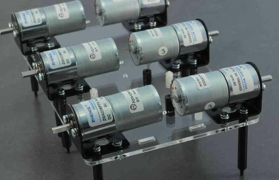
The 6 mounted motors should look like this.
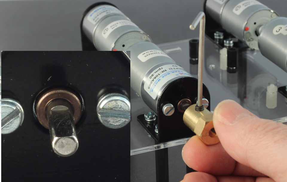
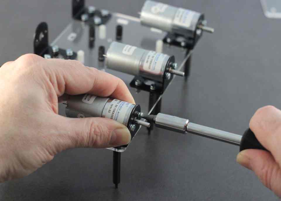
Take a [Motor Hub] and a [Motor grub screw]. Use the [Allen key] to put the grub screw in the hub. It should go in freely, do not use force or it may be cross threaded. If it feels like it is tight to screw in, loosen completely and try again. The motor has a detent or "flat" ground into the shaft. This should be aligned with the grub screw so the screw is perpendicular to the flat.
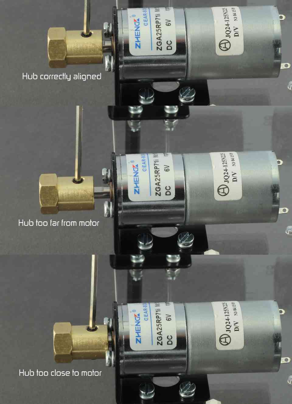
Align the hub so that a small amount of the flat is visible and tighten. Add the second grub screw to the under side of the hub and moderately tighten.
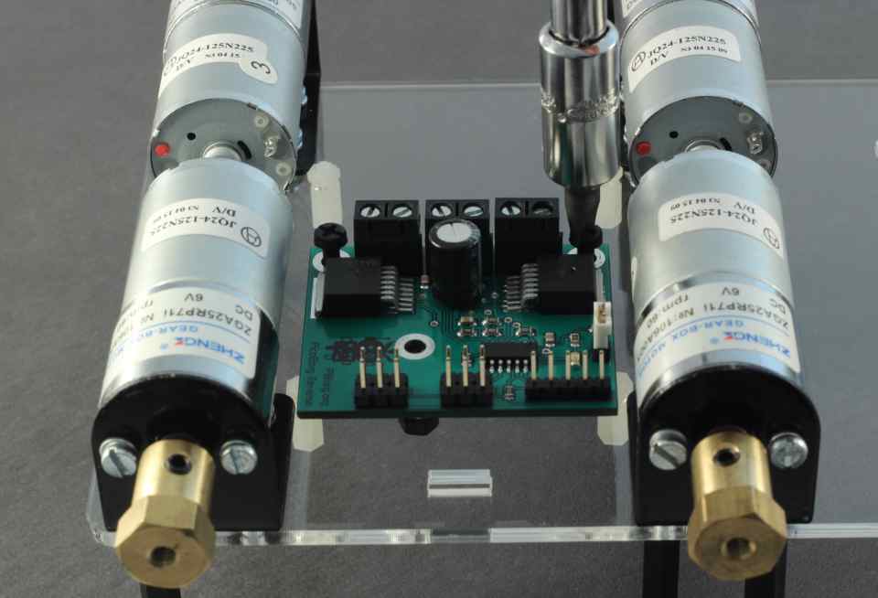
Place the PicoBorg Reverse on the black posts and add 2x [M3 Black Screw]s at the back.
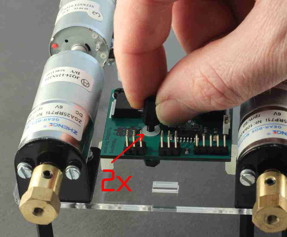
Place 2x [M3 white washers] from the BattBorg post kit over the remaining hole and add the [M3x10 black post] from the same kit. Tighten gently.
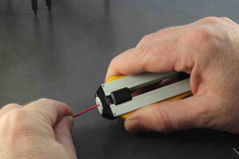
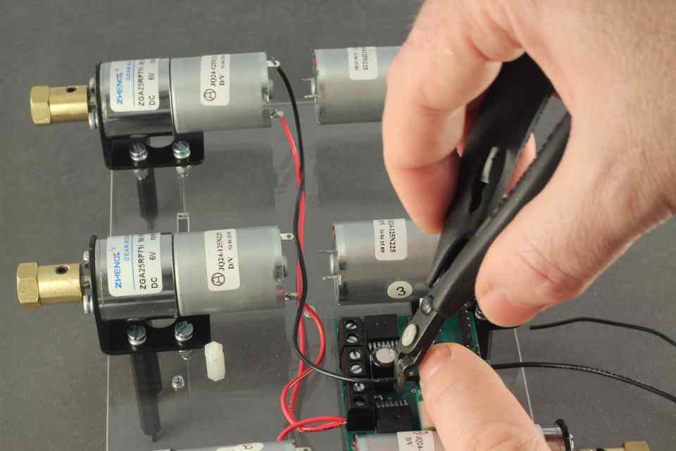
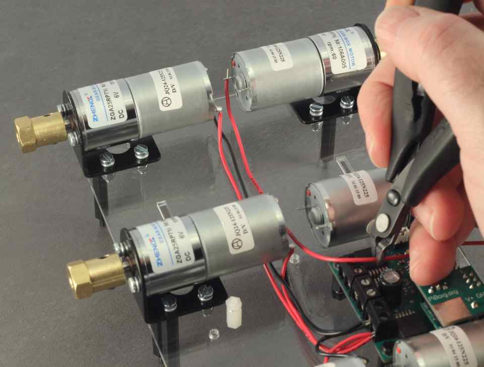
The next part is soldering the wires, which the most time consuming part of assembly. It's best to take your time and do this part well. Take the Red wire, and strip approximately 3mm of insulation from the wire. The easiest way to do this is with a wire stripper. If you use pliers, make sure you do not damage the conductor.
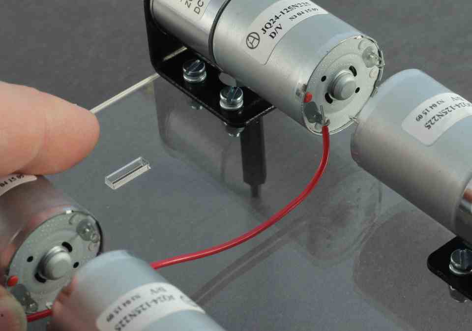
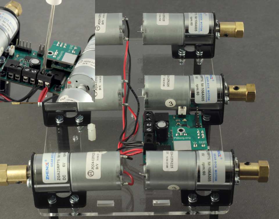
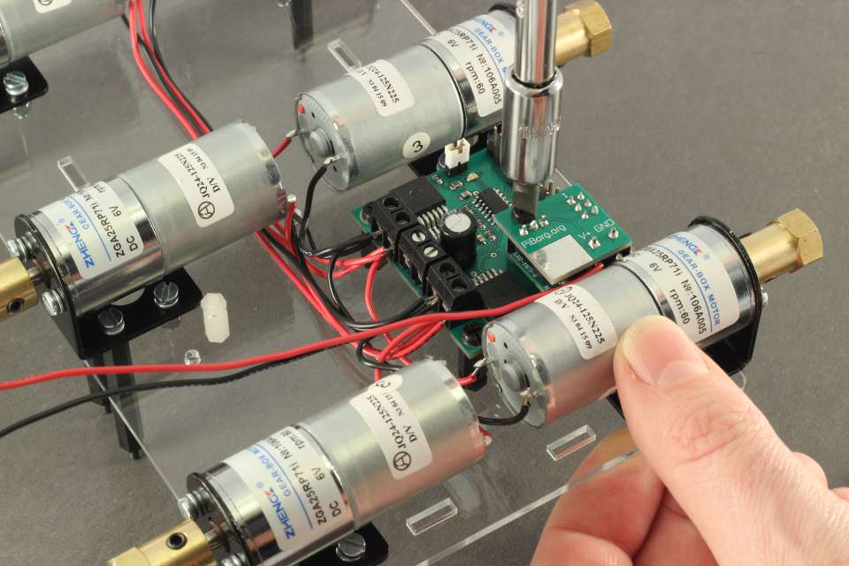
We will first connect up the motor furthest from the PicoBorg Reverse. The motor has a Red dot next to the positive terminal. This is where we will connect the Red wire. Place the exposed conductor through the positive terminal.
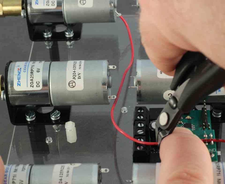
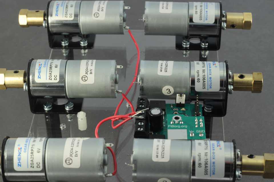
Make the wire follow the path to the M2+ connector on the PicoBorg Reverse. This is the connector furthest from the center. The wire should not be too slack or too tight. See the picture for a good indication of how much slack to give. Once lined up correctly, cut the cable approximately 10-15mm beyond the edge of the board.
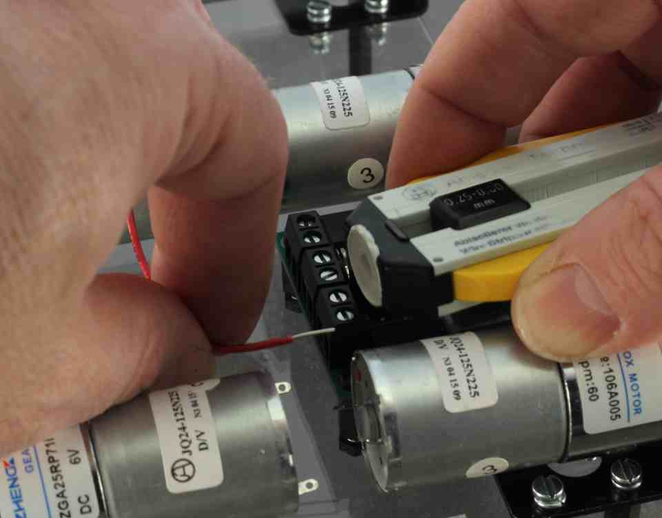
Strip approximately 8mm for connector side. This is to give a good amount of connection in the screw terminal, as we will be placing three cables in one connector hole.
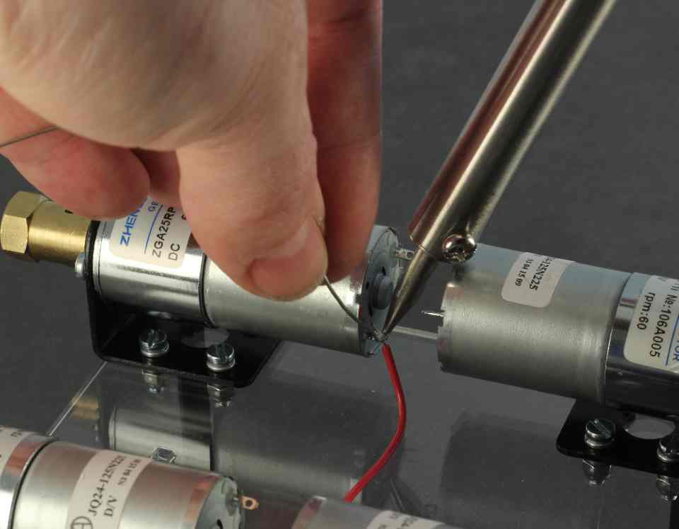
Solder the positive connection to the motor. Be careful not to drip or spray solder on to the Steel plate (a small piece of cardboard or similar is useful to protect the Steel plate here). If you are new to soldering, it's a good idea to have someone help you.
Repeat for other two motors on the same side.
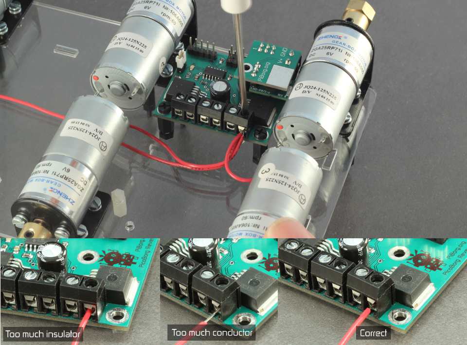
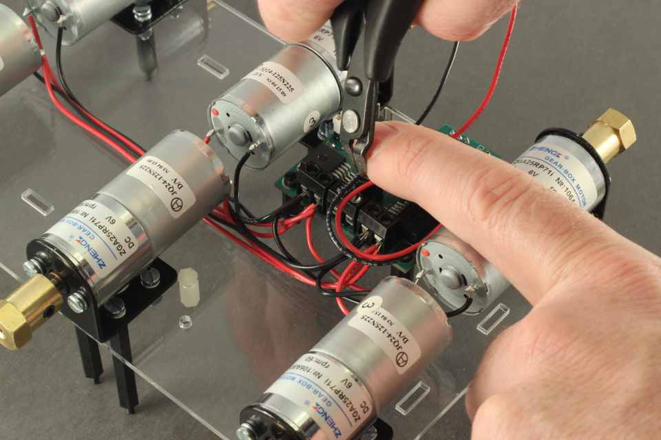
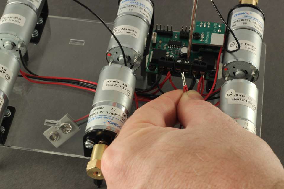
Unscrew the connector so that the connector slot is amply opened. Place all three conductors in the M2+ connector. Ensure they are in as deep as they will go, and tighten. If the Red insulator is being 'bitten' by the clamp, you will need to strip slightly more insulator off the cable. If there is too much conductor exposed, trim the ends off the conductor slightly. The pictures give a good indication of this. Once tightened, gently pull on each individual cable to ensure it has been properly 'bitten' by the clamp of the screw connector. If not, release connector and try again.
Take the black cable, and route it to the remaining connector on the motor. This will go to the terminal M2- on the PicoBorg Reverse. Solder motor side and strip PicoBorg Reverse side as before.
Repeat for all three motors on this side. Screw in the three cables to the connector.
Take the Red cable again and repeat for the other side - Red to Red dot on the Motor, but this time connecting to the M1+ on the PicoBorg Reverse. Solder the three motor side connections.
Tighten these three red connections in to M1+.
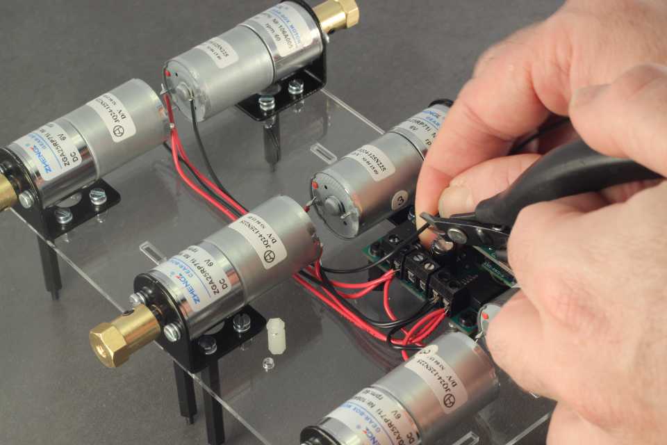
Take the black cable again, and connect the three remaining motor connections to M1-
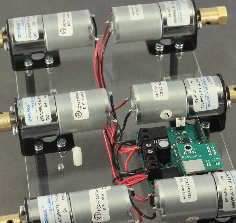
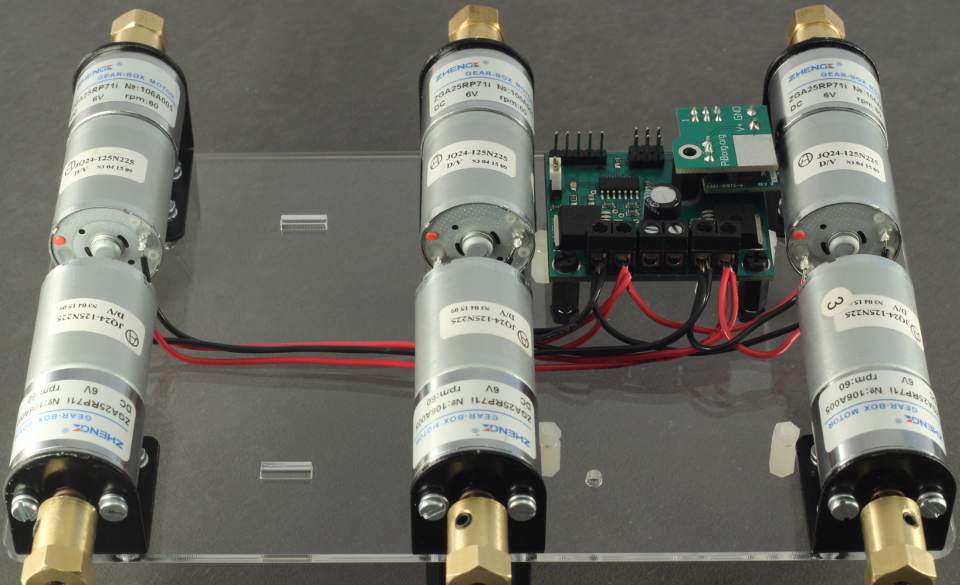
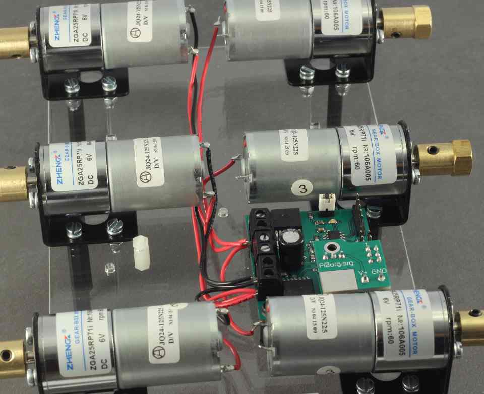
Completed motor connections should look as per images.
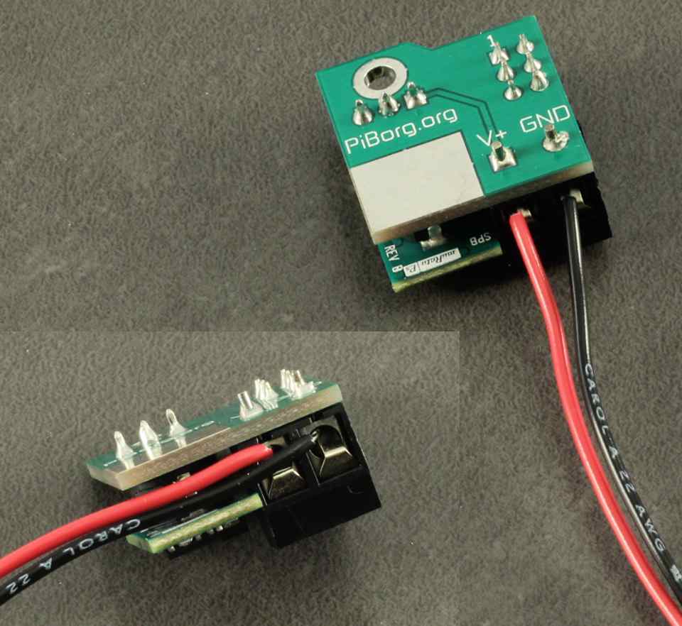
Take the BattBorg, strip approx 8mm from the ends of the Red and Black cables and insert and tighten. Ensure as before, the connectors are gripping the conductor, not the insulator, and it is important here that the insulator is not too long, as it could potentially short to the motor, or to each other. Once tightened, gently pull on each individual cable to ensure it has been properly 'bitten' by the clamp of the screw connector. If not, release connector and try again. Bend the cables towards the silver panel and between the two layers of the PCB as per image.
Plug the BattBorg into the PicoBorg Reverse. Ensure the 6 pin connector on the BattBorg is directly over the 6 pins. The screw hole in the BattBorg should roughly align with the black post.
Screw in the [M3 Black Screw] from the BattBorg post kit. Ensure again that the V+ and GND cables are not shorting on the motor, on each other or the silver pad on the BattBorg PCB.
Route the remaining Red and Black cable to the V+ and GND connectors on the PicoBorg Reverse with a small amount of free loop. Trim the cable to approx 10-15mm beyond the connectors. Strip approx 8mm from the cable ends.
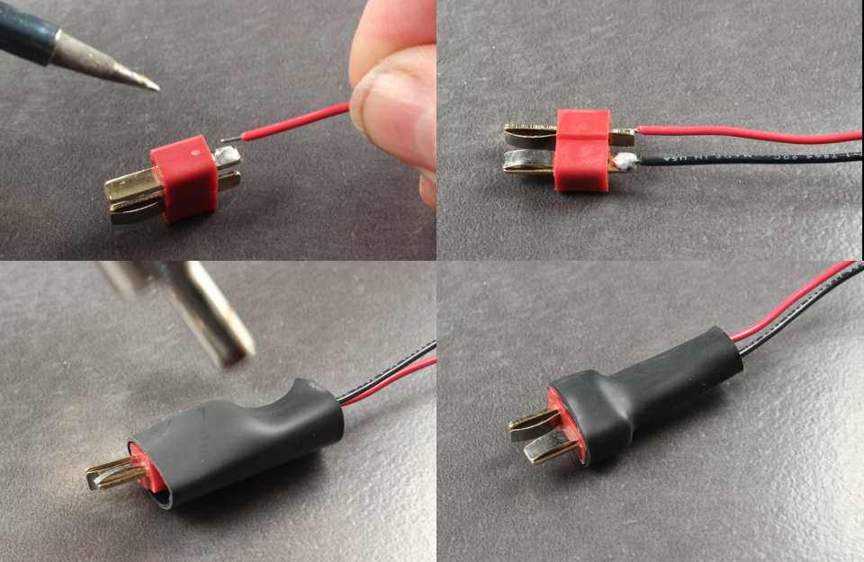
Take the Male Deans plug connector (the one with protruding pins on both sides) and solder a 15cm length of Red wire to the pin labelled +. Solder a 15cm length of black wire to the terminal labelled -. Be careful not to touch the pins of the connector as they absorb a lot of heat and take a long time to cool.
Take one of the 30mm pieces of heatshrink and place it over the soldered plug. Align it so it is flush with the front of the deans plug. Preferably use a hot air blower, or heat from a safe distance from a lighter flame, or radiated heat from a soldering iron to shrink the heatshrink as shown in the last picture.
Take the connector you have just soldered and place it through the hole in the center of the metal plate. You can use some small heatshrink or a very small amount of electrical tape to protect the cables from wearing in the plate.
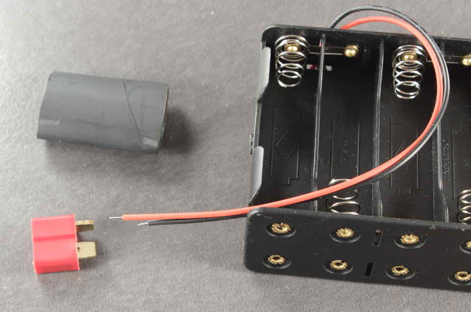
Solder the female deans plug connector to the 12xAA battery pack. Again, Red to +, Black to -. Place heatshrink over the connector and set aside for later.
Connect both the Red BattBorg cable, and the Red cable from the battery strap to the V+ terminal on the PicoBorg Reverse. Connect the Black BattBorg cable and the Black cable of the battery strap to the GND connection on the PicoBorg Reverse. Tighten both screws and pull gently to ensure the connector clamp has bitten. Ensure again that the insulator and conductor lengths are correct.
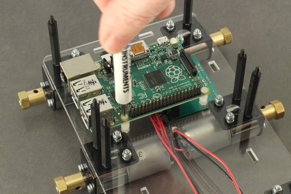
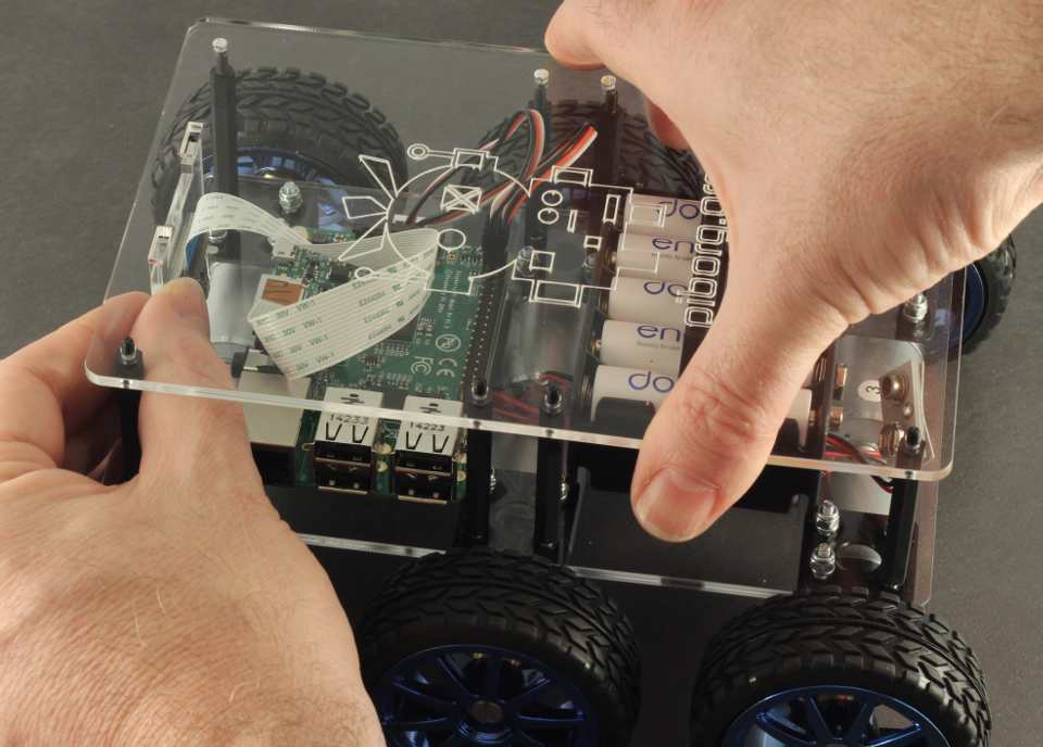
Place the Raspberry Pi (with it's memory card already installed) over the clear posts. The GPIO pins of the Raspberry Pi should be towards the center of the assembly. Add the 4x[M2.5 Screws] for the model B+ or 2x[M2.5 Screws] if you have a model B.
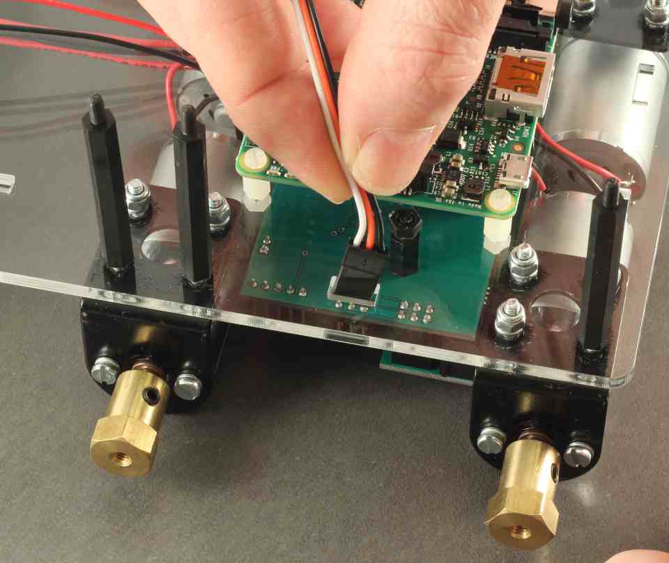
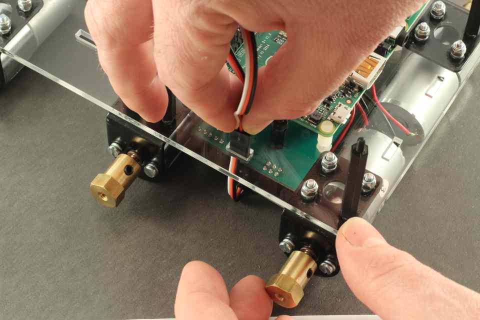
Take one of the PicoBorg Reverse [Comms cables] and pass it through the comms hole in the Steel Plate. Orient the cable so that the white cable is on the side of the middle motor.
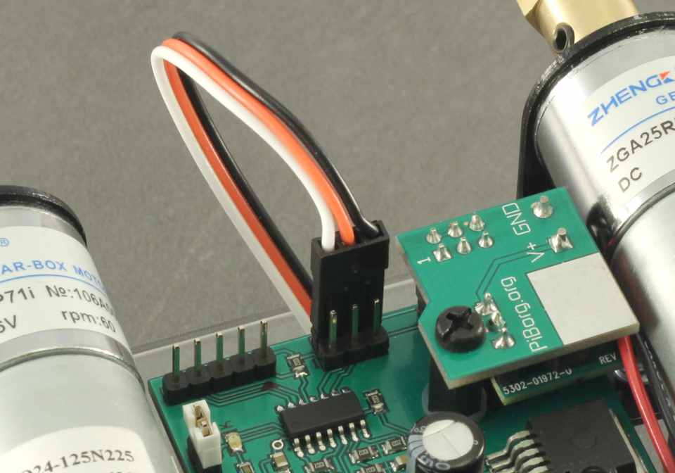
Turn the assembly upside down and plug the cable into the back 3 pins of the 6 pin connector on the PicoBorg Reverse. This is white on Pin 2.
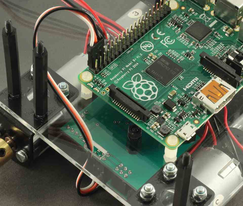
On the Raspberry Pi connector side, plug the connector in so the white pin is also in Pin 2.
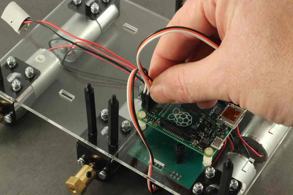
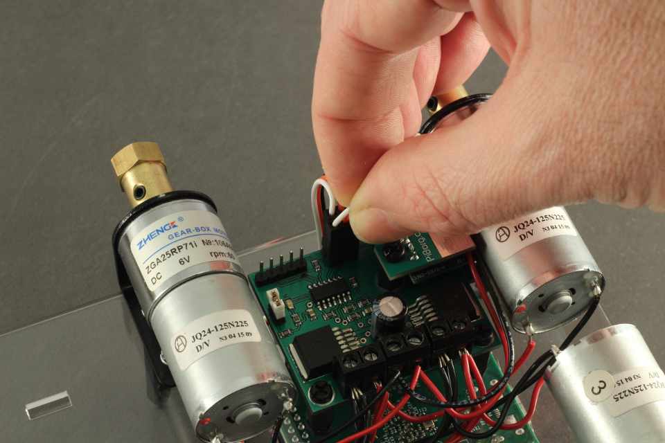
Take the other PicoBorg Reverse [Comms cables] and connect the white to Pin1 of the Raspberry Pi
Pass the comms cable through the hole in the Steel plate next to the other cable.
Connect the other end to Pin1 of the PicoBorg Reverse
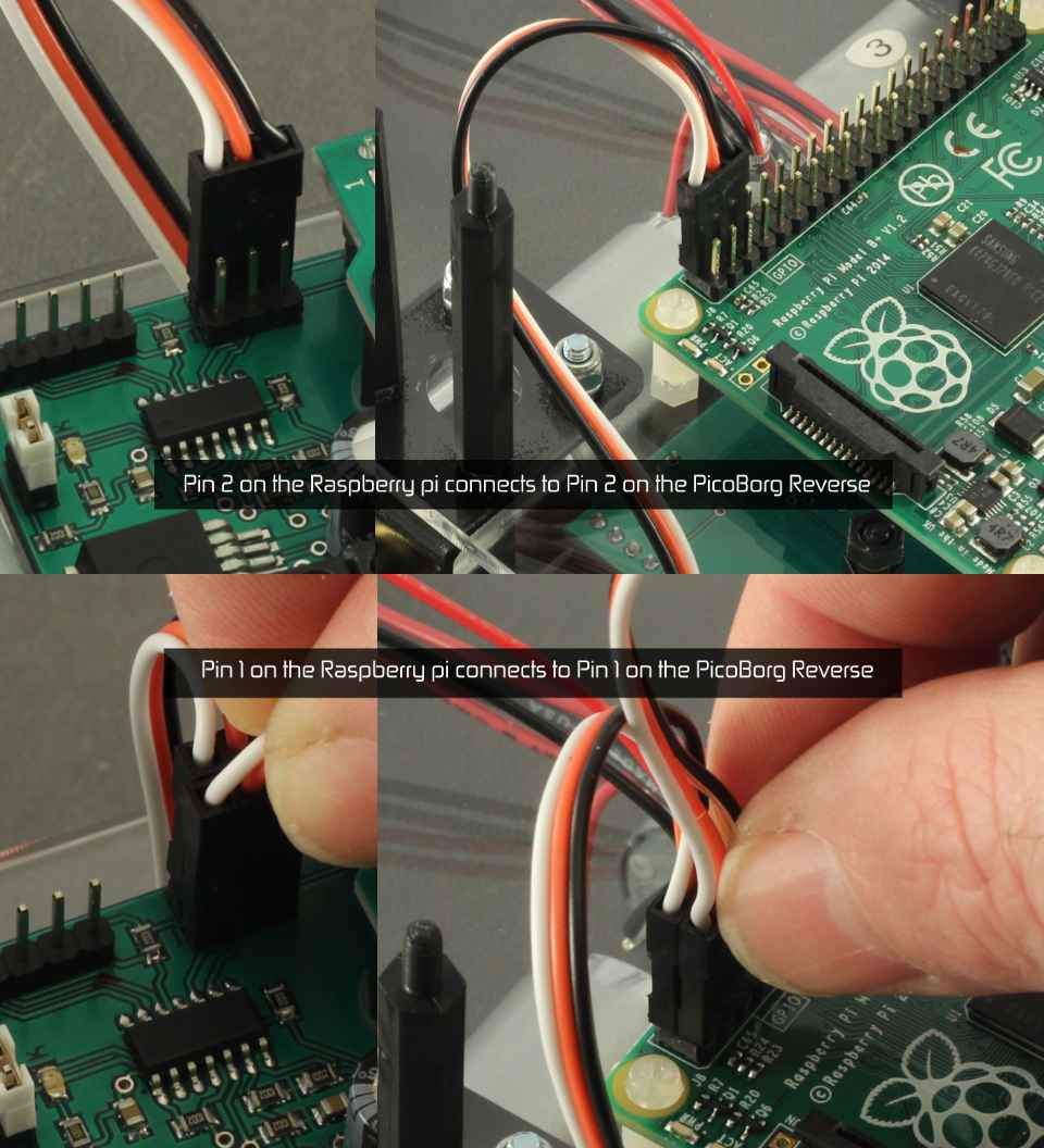
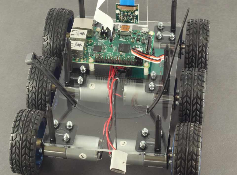
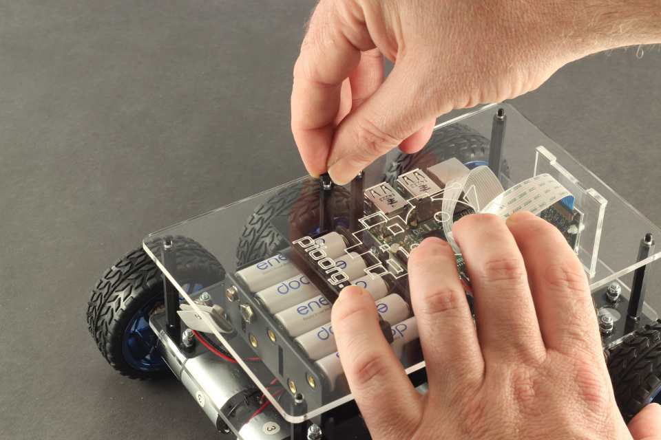
Double Check connections Pin1 to Pin1 and Pin2 to Pin2 as per image.
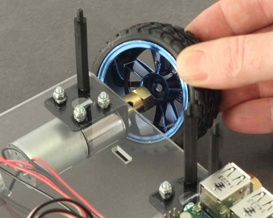
We will now fit the wheels. Hold the motor that you are adding the wheel to with one hand and the wheel in the other. Align the hexagonal patterns on the wheel and hub, and with a very small amount of pressure, the wheel should sit on.
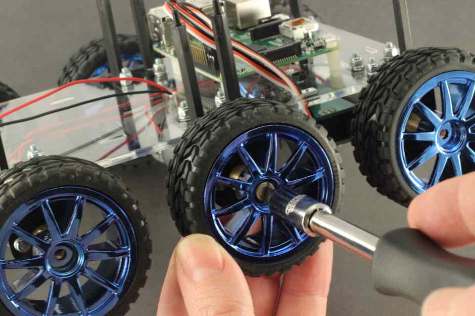
Take the M4 Phillips screws and screw them into the hubs to hold the wheels in. Be careful not to cross thread. If it feels like it is hard to screw them on, unscrew and try again.
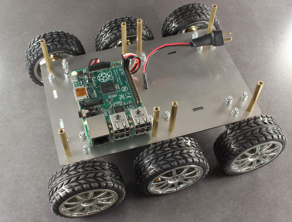
The assembly should now look like this.
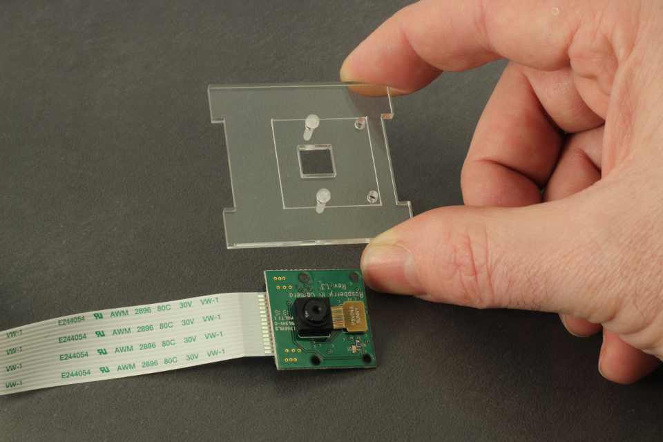
If you have a Raspberry Pi Camera, take the Perspex camera holder and add the 2x[M2x8 Nylon screw]s to the center two holes.
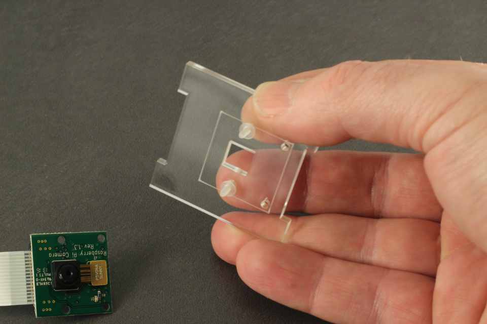
Add the 2x [M2 Washers] to the inside of the Perspex camera mount.
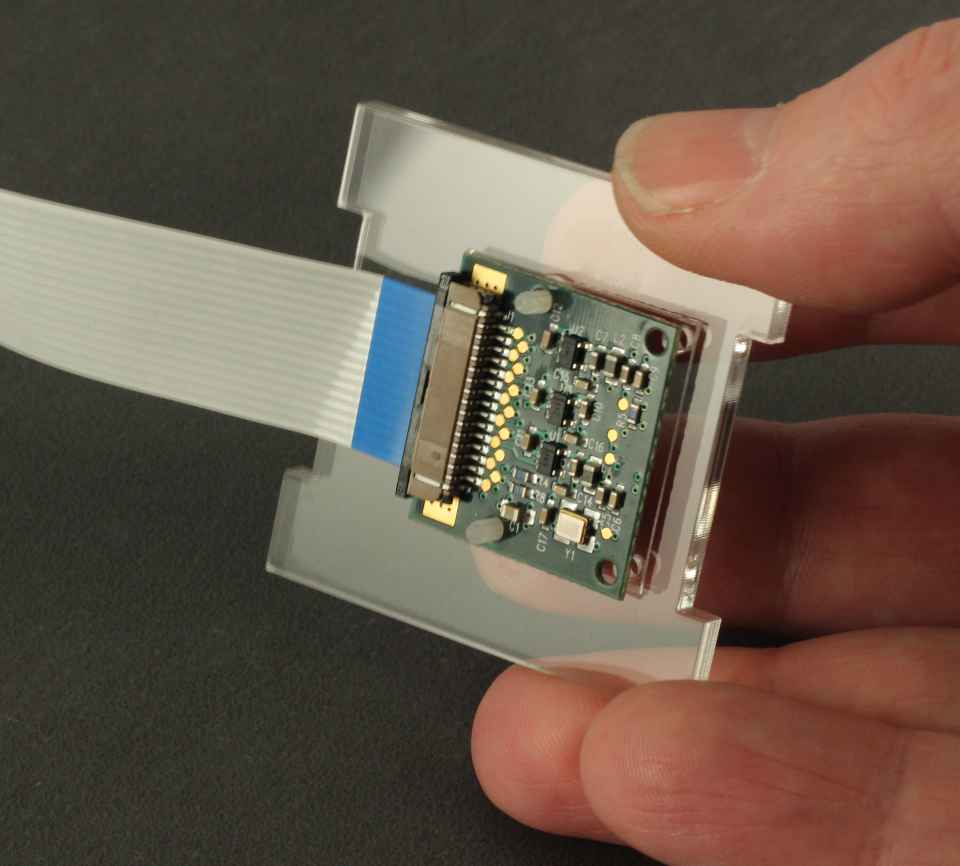
Add the Raspberry Pi camera to the camera mount. It should be aligned with the box cut out and the bottom two holes. We will only use the center two holes here.
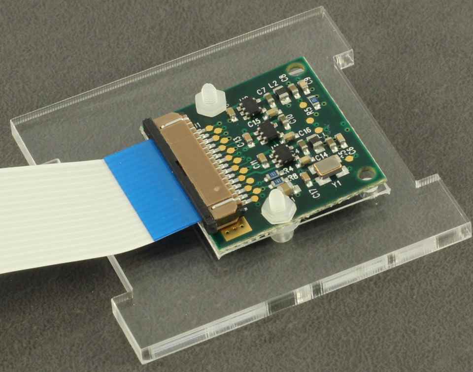
Carefully place the [M2 Nut]s on the back of the camera. Tighten gently. The board should not begin to flex, if it does, ensure you have the washers on the correct side.
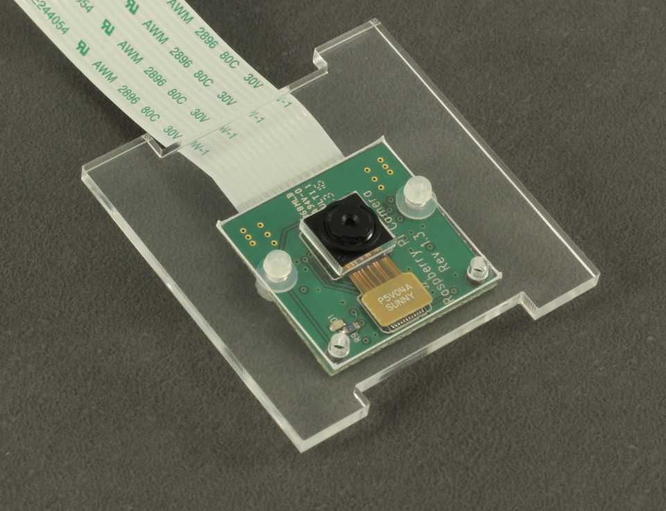
The camera module should look like this.
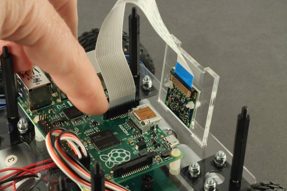
Place the camera on its mount into the Steel plate base with the cable side pointing upwards. Plug the camera cable into the Raspberry Pi as per Raspberry Pi foundations instructions.
*Note It should not be difficult to slot the Perspex camera mount in to the base. If it is, check alignment carefully. The camera module should be a snug fit to minimise vibrations, but if it will not sit in the mounting holes, removing the edges of the perspex will help. You can do this with fine ~600 grit wet and dry sandpaper. It should only require a small amount of sanding. Remove the camera module before sanding!
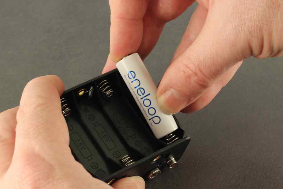
Insert 12x AA batteries into the battery holder. We recommend rechargeable batteries. All the batteries should be the same type and age. Be careful not to short out the contacts on anything metal once they are installed.
Place the Reusable cable tie through the battery slot in the Bottom Plate, between the motor cables and the Plate, then back up through the other battery slot. Also ensure the battery connector with the deans plug on it is pulled taught, and is sitting over the back of the assembly.
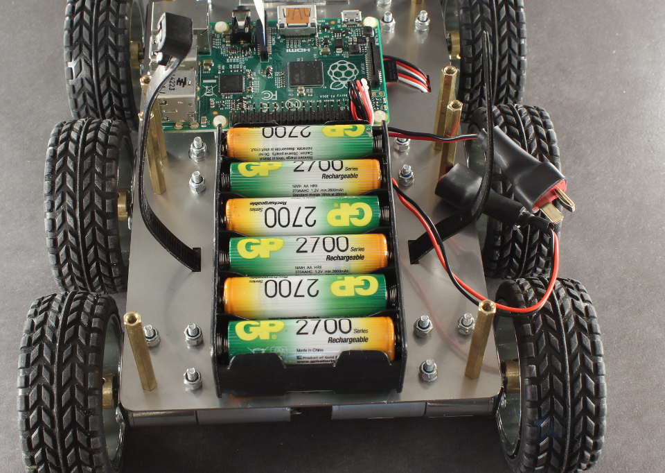
Place the battery pack between the two rectangular cut outs. Thread the cable tie end through the zip end opening.
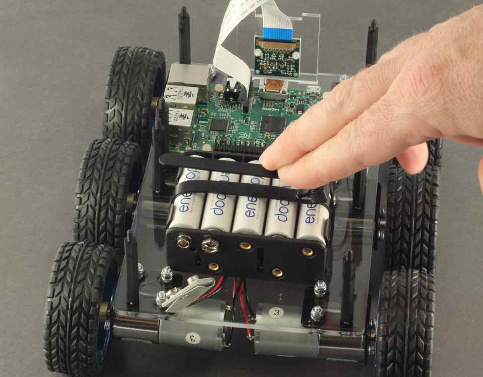
Tighten the cable tie, and bend the end of the tie so it doesn't point straight up. Over time this will naturally bend, but initially it will be difficult to put the top on in the next step.
Place the top Steel plate on. Hold the camera assembly with one hand and align to the cut outs in the top. It may be required to put a small amount of force on the posts to align the holes and post threads.
Whilst maintaining a small amount of pressure on the top steel plate, screw on the 8x[M3 Brass Screw]s
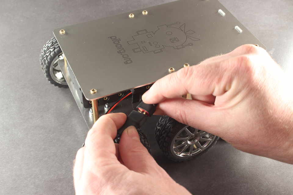
We are just about ready to go! It's a good idea to visually inspect the wiring, double check connections and polarity before powering on. When you are happy all is correct, ensure the correct direction of the battery pack connector and plug in.
Pre-build steps
Once built, it is near impossible to access the HDMI slot, power slot etc. It is recommended to set up the software first, such as the Raspberry Pi camera, software for any Wifi or bluetooth dongle you might want to use and anything you might need/want to run such as PicoBorg Reverse software and any DiddyBorg scripts. A small guide is here which will get you going with some example scripts.
Building the DiddyBorg Metal Edition
Building DiddyBorg Metal Edition is very similar to building DiddyBorg Classic, so we will use images interchangeably. Where there is a difference, it is noted and different images are used.
The Stainless Steel top and bottom are laser cut, and are covered with a protective oil, which you can remove with IPA or stainless cleaner. The Kit includes a small towell which is ideal for wiping the steel clean.
You will need to place 4x[M3x12 Cheese screw]s and 4x[M3 Spring washer]s into a motor mount. Make sure the orientation of the motor mount is as per the picture. *Please note the [M3x12 Cheese screw]s are different from the [M3x8 Cheese screw]s
Take the base board and orient it so that the short thick rectangular cut out is at the top left, as in the picture. Place the motor mount on top, with the rounded edge facing up, and locate the four screws in the holes of the steel.
Hold the screws in with your finger tips, and turn the board around
Place a [M3x40 Brass post] on the screw which is closest to the corner of the Steel Plate. Tighten this gently with your fingers. We will tighten this correctly later.
*Please note there is no spring washer on this side
Place 3x[M3 Spring washer]s and 3x[M3 Lock nut]s on the remaining holes, and tighten gently with your fingers.
Do the same for the middle motor mount, with the exception that there are two [M3x40 Brass post]s, on the two holes towards the outside edge of the Steel Plate. Again, the posts have a spring washer only on one side.
Repeat above for remaining four motor mounts as per image.
Position the mounts so that they are aligned - that is, they should be level on the same plane. The image highlights this. Once the alignment is correct, tighten the Brass posts gently by hand. Do not overtighten, or you could strip the thread from the Brass post. We just need to tighten to the point where we have crushed the spring washer underneath so it is flat.
Tighten the screws using a flat bladed screw driver and a 5.5mm socket or spanner. Do not overtighten. Again, tighten just to the point where the spring washers are flat. This is a particularly fiddly part of the assembly, so you might need a third hand!
Orient the board so it has the posts facing up. This image also shows the spring washers correctly crushed.
Place the 3x[M3x10 black post]s in the holes as shown in the image. They should be oriented so the post is facing downwards. Add and gently tighten the 3x[M3 Black Nylon nut]s on top.
If you have a Raspberry Pi model B+, place the 4x [M2.5x10 white post]s in the four holes as shown in the top diagram. Add the 4x [M2.5 Nut]s. If you have a model B, place 2x of the [M2.5x10 white post]s in the two holes shown in the bottom diagram. Add the 2x [M2.5 Nut]s.
Orient the board so that the long posts are facing down.
Take 2x[M3x8 Cheese screw]s, add 2x[M3 Spring washer]s to the screws. Place a motor in the mount, and align the motor holes with the mount. Insert and moderately tighten the screws until the washers have collapsed well.
*Note the motors are in the same orientation - that is, with the stickers facing up. This keeps the polarity of the motor connections consistent which will be helpful soon.
Repeat for all 6 motors.
The 6 mounted motors should look like this.
Take a [Motor Hub] and a [Motor grub screw]. Use the [Allen key] to put the grub screw in the hub. It should go in freely, do not use force or it may be cross threaded. If it feels like it is tight to screw in, loosen completely and try again. The motor has a detent or "flat" ground into the shaft. This should be aligned with the grub screw so the screw is perpendicular to the flat.
Align the hub so that a small amount of the flat is visible and tighten. Add the second grub screw to the under side of the hub and moderately tighten.
Place the PicoBorg Reverse on the black posts and add 2x [M3 Black Screw]s at the back.
Place 2x [M3 white washers] from the BattBorg post kit over the remaining hole and add the [M3x10 black post] from the same kit. Tighten gently.
The next part is soldering the wires, which the most time consuming part of assembly. It's best to take your time and do this part well. Take the Red wire, and strip approximately 3mm of insulation from the wire. The easiest way to do this is with a wire stripper. If you use pliers, make sure you do not damage the conductor.
We will first connect up the motor furthest from the PicoBorg Reverse. The motor has a Red dot next to the positive terminal. This is where we will connect the Red wire. Place the exposed conductor through the positive terminal.
Make the wire follow the path to the M2+ connector on the PicoBorg Reverse. This is the connector furthest from the center. The wire should not be too slack or too tight. See the picture for a good indication of how much slack to give. Once lined up correctly, cut the cable approximately 10-15mm beyond the edge of the board.
Strip approximately 8mm for connector side. This is to give a good amount of connection in the screw terminal, as we will be placing three cables in one connector hole.
Solder the positive connection to the motor. Be careful not to drip or spray solder on to the Steel plate (a small piece of cardboard or similar is useful to protect the Steel plate here). If you are new to soldering, it's a good idea to have someone help you.
Repeat for other two motors on the same side.
Unscrew the connector so that the connector slot is amply opened. Place all three conductors in the M2+ connector. Ensure they are in as deep as they will go, and tighten. If the Red insulator is being 'bitten' by the clamp, you will need to strip slightly more insulator off the cable. If there is too much conductor exposed, trim the ends off the conductor slightly. The pictures give a good indication of this. Once tightened, gently pull on each individual cable to ensure it has been properly 'bitten' by the clamp of the screw connector. If not, release connector and try again.
Take the black cable, and route it to the remaining connector on the motor. This will go to the terminal M2- on the PicoBorg Reverse. Solder motor side and strip PicoBorg Reverse side as before.
Repeat for all three motors on this side. Screw in the three cables to the connector.
Take the Red cable again and repeat for the other side - Red to Red dot on the Motor, but this time connecting to the M1+ on the PicoBorg Reverse. Solder the three motor side connections.
Tighten these three red connections in to M1+.
Take the black cable again, and connect the three remaining motor connections to M1-
Completed motor connections should look as per images.
Take the BattBorg, strip approx 8mm from the ends of the Red and Black cables and insert and tighten. Ensure as before, the connectors are gripping the conductor, not the insulator, and it is important here that the insulator is not too long, as it could potentially short to the motor, or to each other. Once tightened, gently pull on each individual cable to ensure it has been properly 'bitten' by the clamp of the screw connector. If not, release connector and try again. Bend the cables towards the silver panel and between the two layers of the PCB as per image.
Plug the BattBorg into the PicoBorg Reverse. Ensure the 6 pin connector on the BattBorg is directly over the 6 pins. The screw hole in the BattBorg should roughly align with the black post.
Screw in the [M3 Black Screw] from the BattBorg post kit. Ensure again that the V+ and GND cables are not shorting on the motor, on each other or the silver pad on the BattBorg PCB.
Route the remaining Red and Black cable to the V+ and GND connectors on the PicoBorg Reverse with a small amount of free loop. Trim the cable to approx 10-15mm beyond the connectors. Strip approx 8mm from the cable ends.
Take the Male Deans plug connector (the one with protruding pins on both sides) and solder a 15cm length of Red wire to the pin labelled +. Solder a 15cm length of black wire to the terminal labelled -. Be careful not to touch the pins of the connector as they absorb a lot of heat and take a long time to cool.
Take one of the 30mm pieces of heatshrink and place it over the soldered plug. Align it so it is flush with the front of the deans plug. Preferably use a hot air blower, or heat from a safe distance from a lighter flame, or radiated heat from a soldering iron to shrink the heatshrink as shown in the last picture.
Take the connector you have just soldered and place it through the hole in the center of the metal plate. You can use some small heatshrink or a very small amount of electrical tape to protect the cables from wearing in the plate.
Solder the female deans plug connector to the 12xAA battery pack. Again, Red to +, Black to -. Place heatshrink over the connector and set aside for later.
Connect both the Red BattBorg cable, and the Red cable from the battery strap to the V+ terminal on the PicoBorg Reverse. Connect the Black BattBorg cable and the Black cable of the battery strap to the GND connection on the PicoBorg Reverse. Tighten both screws and pull gently to ensure the connector clamp has bitten. Ensure again that the insulator and conductor lengths are correct.
Place the Raspberry Pi (with it's memory card already installed) over the clear posts. The GPIO pins of the Raspberry Pi should be towards the center of the assembly. Add the 4x[M2.5 Screws] for the model B+ or 2x[M2.5 Screws] if you have a model B.
Take one of the PicoBorg Reverse [Comms cables] and pass it through the comms hole in the Steel Plate. Orient the cable so that the white cable is on the side of the middle motor.
Turn the assembly upside down and plug the cable into the back 3 pins of the 6 pin connector on the PicoBorg Reverse. This is white on Pin 2.
On the Raspberry Pi connector side, plug the connector in so the white pin is also in Pin 2.
Take the other PicoBorg Reverse [Comms cables] and connect the white to Pin1 of the Raspberry Pi
Pass the comms cable through the hole in the Steel plate next to the other cable.
Connect the other end to Pin1 of the PicoBorg Reverse
Double Check connections Pin1 to Pin1 and Pin2 to Pin2 as per image.
We will now fit the wheels. Hold the motor that you are adding the wheel to with one hand and the wheel in the other. Align the hexagonal patterns on the wheel and hub, and with a very small amount of pressure, the wheel should sit on.
Take the M4 Phillips screws and screw them into the hubs to hold the wheels in. Be careful not to cross thread. If it feels like it is hard to screw them on, unscrew and try again.
The assembly should now look like this.
If you have a Raspberry Pi Camera, take the Perspex camera holder and add the 2x[M2x8 Nylon screw]s to the center two holes.
Add the 2x [M2 Washers] to the inside of the Perspex camera mount.
Add the Raspberry Pi camera to the camera mount. It should be aligned with the box cut out and the bottom two holes. We will only use the center two holes here.
Carefully place the [M2 Nut]s on the back of the camera. Tighten gently. The board should not begin to flex, if it does, ensure you have the washers on the correct side.
The camera module should look like this.
Place the camera on its mount into the Steel plate base with the cable side pointing upwards. Plug the camera cable into the Raspberry Pi as per Raspberry Pi foundations instructions.
*Note It should not be difficult to slot the Perspex camera mount in to the base. If it is, check alignment carefully. The camera module should be a snug fit to minimise vibrations, but if it will not sit in the mounting holes, removing the edges of the perspex will help. You can do this with fine ~600 grit wet and dry sandpaper. It should only require a small amount of sanding. Remove the camera module before sanding!
Insert 12x AA batteries into the battery holder. We recommend rechargeable batteries. All the batteries should be the same type and age. Be careful not to short out the contacts on anything metal once they are installed.
Place the Reusable cable tie through the battery slot in the Bottom Plate, between the motor cables and the Plate, then back up through the other battery slot. Also ensure the battery connector with the deans plug on it is pulled taught, and is sitting over the back of the assembly.
Place the battery pack between the two rectangular cut outs. Thread the cable tie end through the zip end opening.
Tighten the cable tie, and bend the end of the tie so it doesn't point straight up. Over time this will naturally bend, but initially it will be difficult to put the top on in the next step.
Place the top Steel plate on. Hold the camera assembly with one hand and align to the cut outs in the top. It may be required to put a small amount of force on the posts to align the holes and post threads.
Whilst maintaining a small amount of pressure on the top steel plate, screw on the 8x[M3 Brass Screw]s
We are just about ready to go! It's a good idea to visually inspect the wiring, double check connections and polarity before powering on. When you are happy all is correct, ensure the correct direction of the battery pack connector and plug in.


![[M3x12 Cheese screw]](/images/DiddyBorg/DiddyBorg M3x12 Cheese screw.jpg)
![[M3 Spring washer]](/images/DiddyBorg/DiddyBorg M3 Spring washer.jpg)
![[M3x8 Cheese screw]](/images/DiddyBorg/DiddyBorg M3x8 Cheese screw.jpg)
![[M3x40 Brass post]](/images/DiddyBorg/DiddyBorg M3x40 Brass post.jpg)
![[M3 Lock nut]](/images/DiddyBorg/DiddyBorg M3 Lock nut.jpg)
![[M3x10 black post]](/images/DiddyBorg/DiddyBorg M3x10 black post.jpg)
![[M3 Black Nylon nut]](/images/DiddyBorg/DiddyBorg M3 Black Nylon nut.jpg)
![[M2.5x10 white post]](/images/DiddyBorg/DiddyBorg M2.5x10 white post.jpg)
![[M2.5 Nut]](/images/DiddyBorg/DiddyBorg M2.5 nut.jpg)
![[Motor Hub]](/images/DiddyBorg/DiddyBorg Motor Hub.jpg)
![[Motor grub screw]](/images/DiddyBorg/DiddyBorg Motor grub screw.jpg)
![[Allen key]](/images/DiddyBorg/DiddyBorg Allen key.jpg)
![[M3 Black Screw]](/images/DiddyBorg/DiddyBorg M3 Black Screw.jpg)
![[M3 white washers]](/images/DiddyBorg/DiddyBorg M3 white washers.jpg)
![[M2.5 Screws]](/images/DiddyBorg/DiddyBorg M2.5 Screws.jpg)
![[Comms cables]](/images/DiddyBorg/DiddyBorg Comms cables.jpg)
![[M2x8 Nylon screw]](/images/DiddyBorg/DiddyBorg M2x8 Nylon screw.jpg)
![[M2 Washers]](/images/DiddyBorg/DiddyBorg M2 Washers.jpg)
![[M2 Nut]](/images/DiddyBorg/DiddyBorg M2 Nut.jpg)
![[M3 Brass Screw]](/images/DiddyBorg/DiddyBorg M3 Brass Screw.jpg)