
ThunderBorg - Powerful motor controller mounted to your Raspberry Pi
Installation
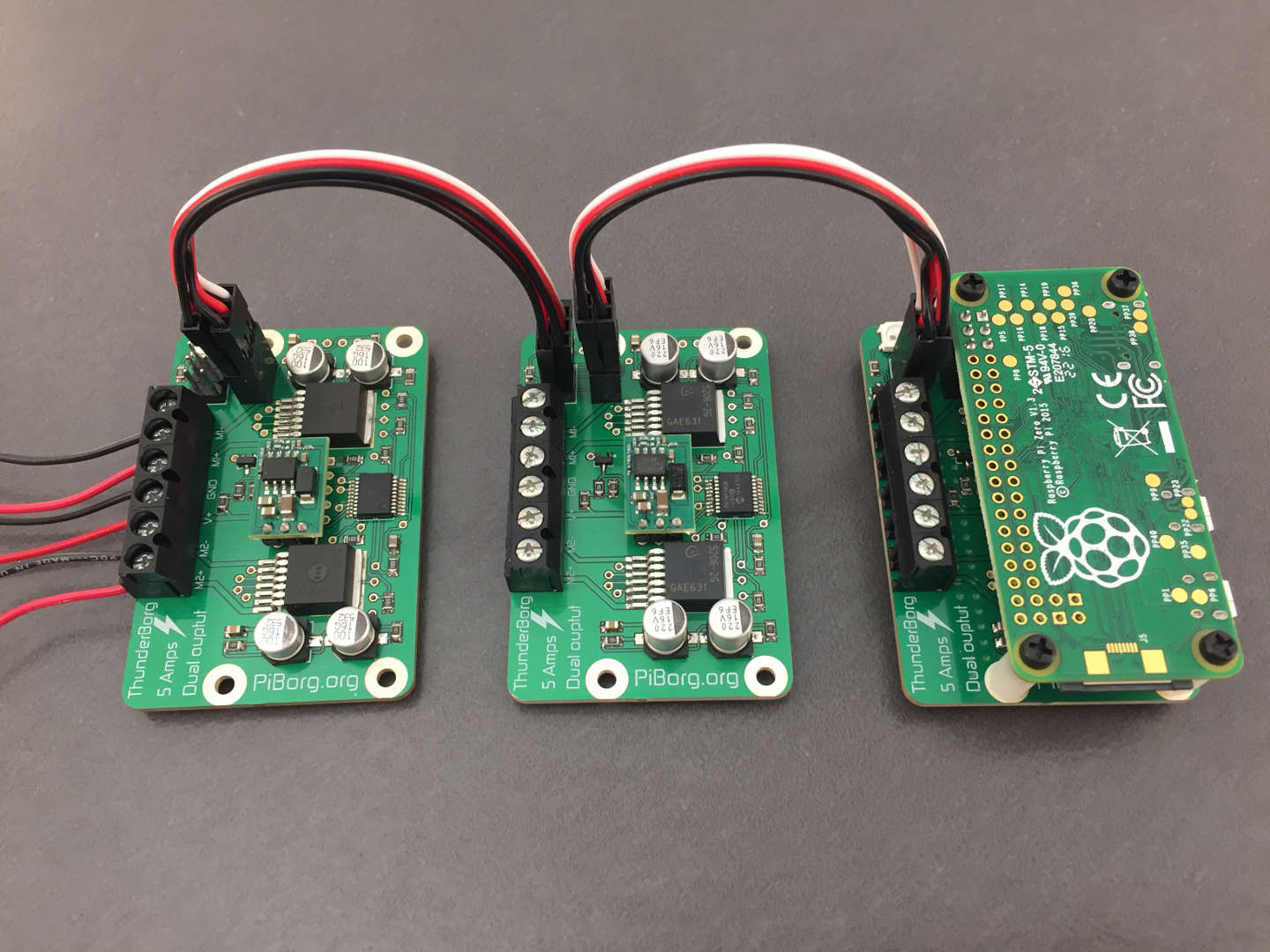
Mounting on the Pi (optional)
With most newer Raspberry Pis it is possible to mount the ThunderBorg directly to your Raspberry Pi: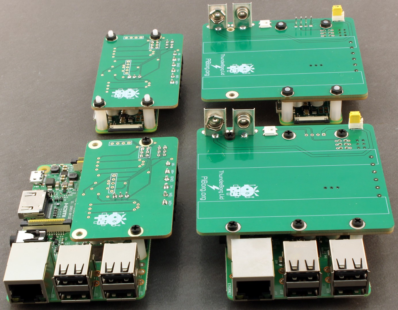
The six-pin socket on the ThunderBorg should fit snuggly on the first six GPIO pins of the Raspberry Pi.
If you are using a Pi Zero you will need to solder pins to the first six GPIO pins before mounting the ZeroBorg.
Make sure the posts are screwed in tight to prevent the ThunderBorg moving around!
Connections
Using cables to the Pi (optional)
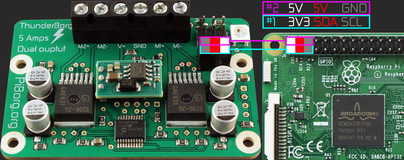
If you are using cables instead of mounting the ThunderBorg you will need to connect the two provided 3-pin cables from the first six GPIO pins on Raspberry Pi to the six-pin socket on the ThunderBorg: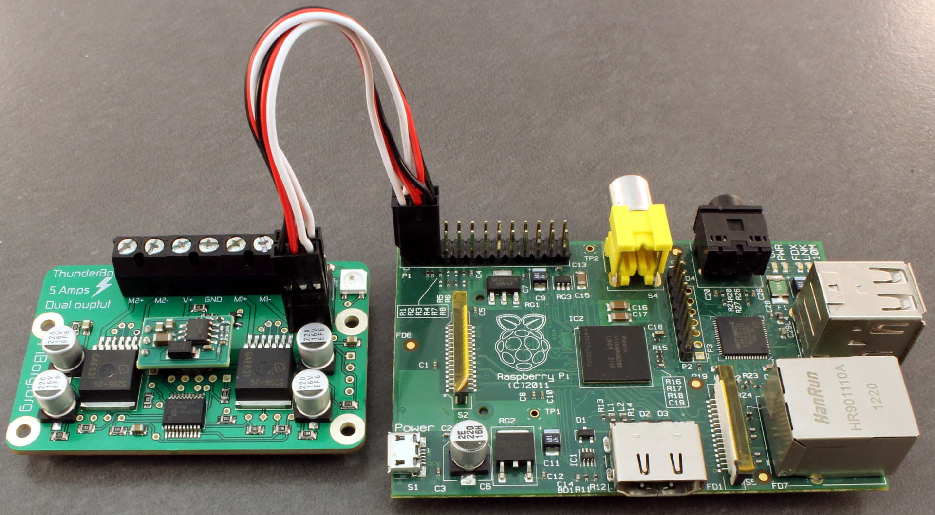
These outlines show an individual 3x1 pin cable (two supplied), the coloured boxes show the colour of the wire (grey is used instead of black in the diagram).
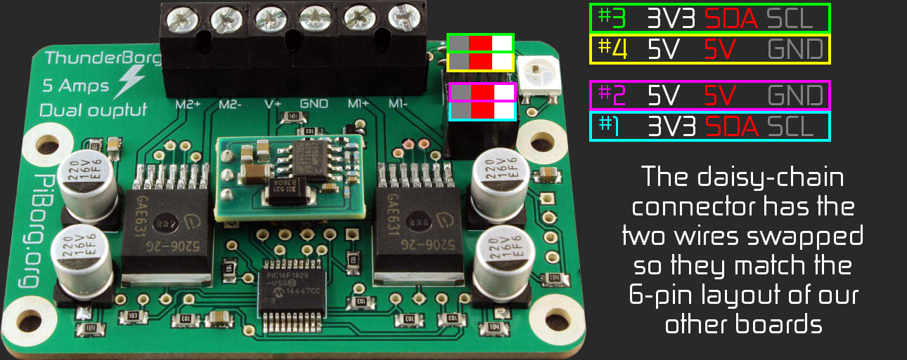
You can also connect additional ThunderBorgs or PiBorg boards by using the six-pin daisy-chain connector, read further down for instructions on configuring the software correctly to run with multiple ThunderBorgs attached.
DC (normal) motors
You will need to add the motors (or only one if you desire) and the battery / power supply to the board like this: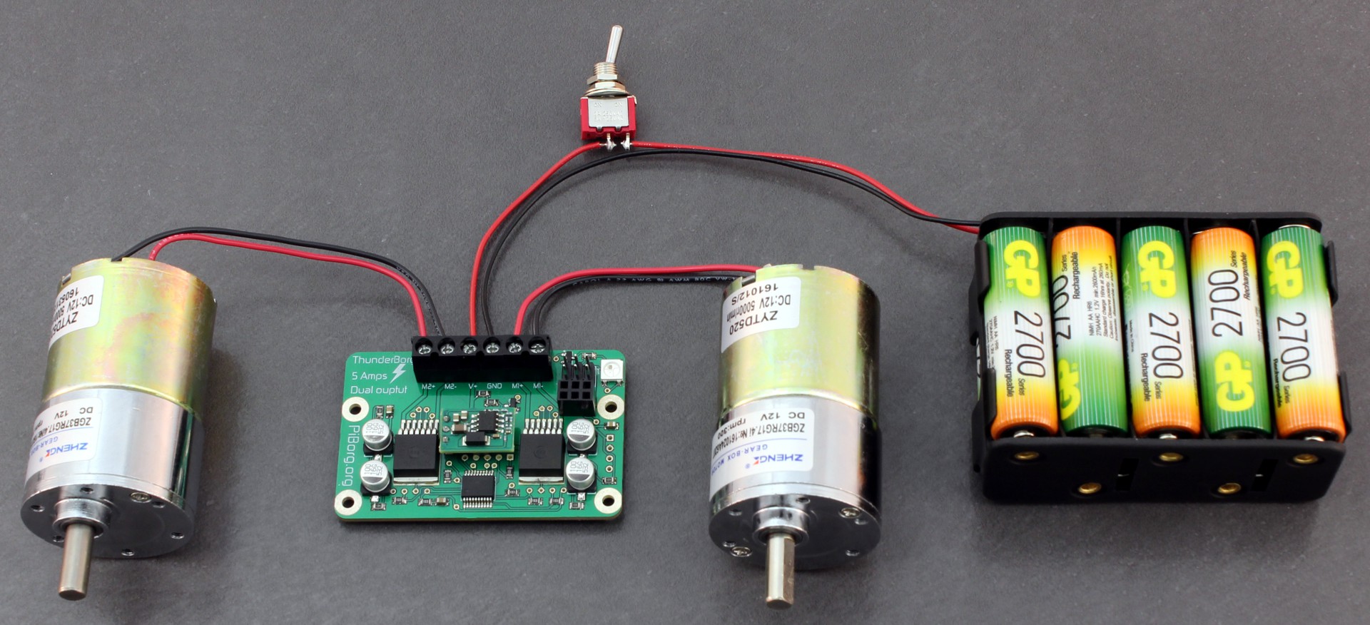
M1 is on the right, M2 is on the left (this is labelled on the board).
The power switch shown is optional, but we would recommend one :)
For those with a ThunderBorg Lid the battery pack can be attached by the 9V connector underneath instead:
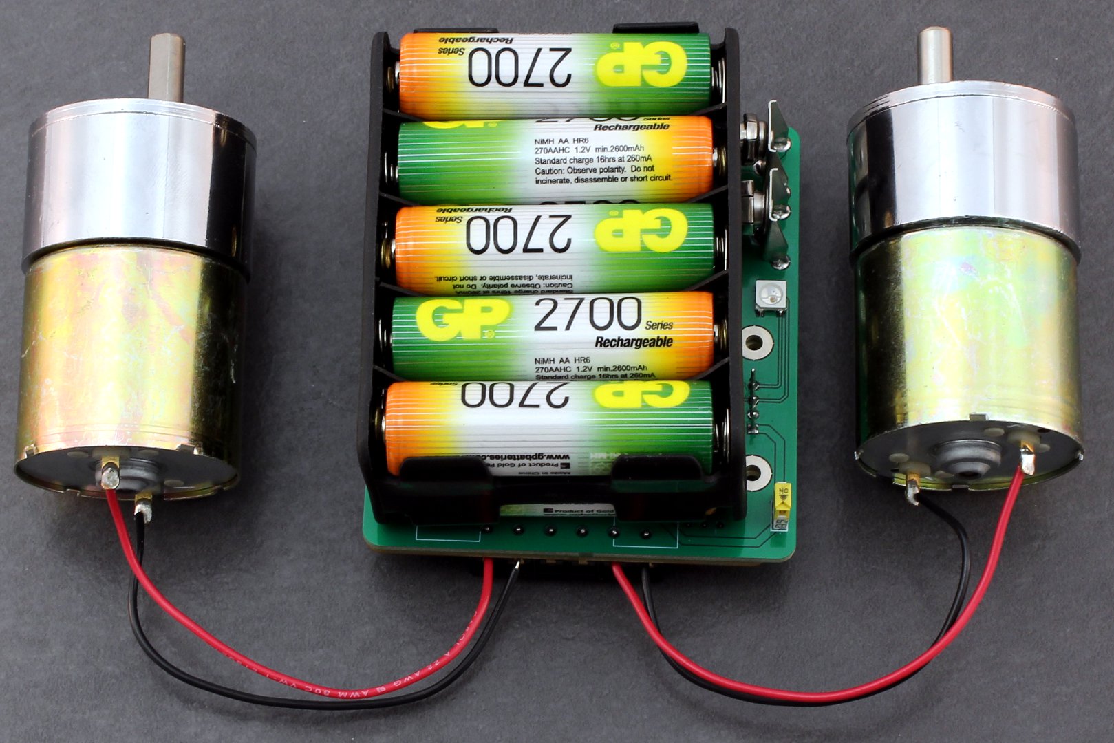
There is no need to add a switch in this case, the ThunderBorg Lid already has one ;)
Stepper motors
You will need to add the motor to both motor outputs, and the battery / power supply to the board like this: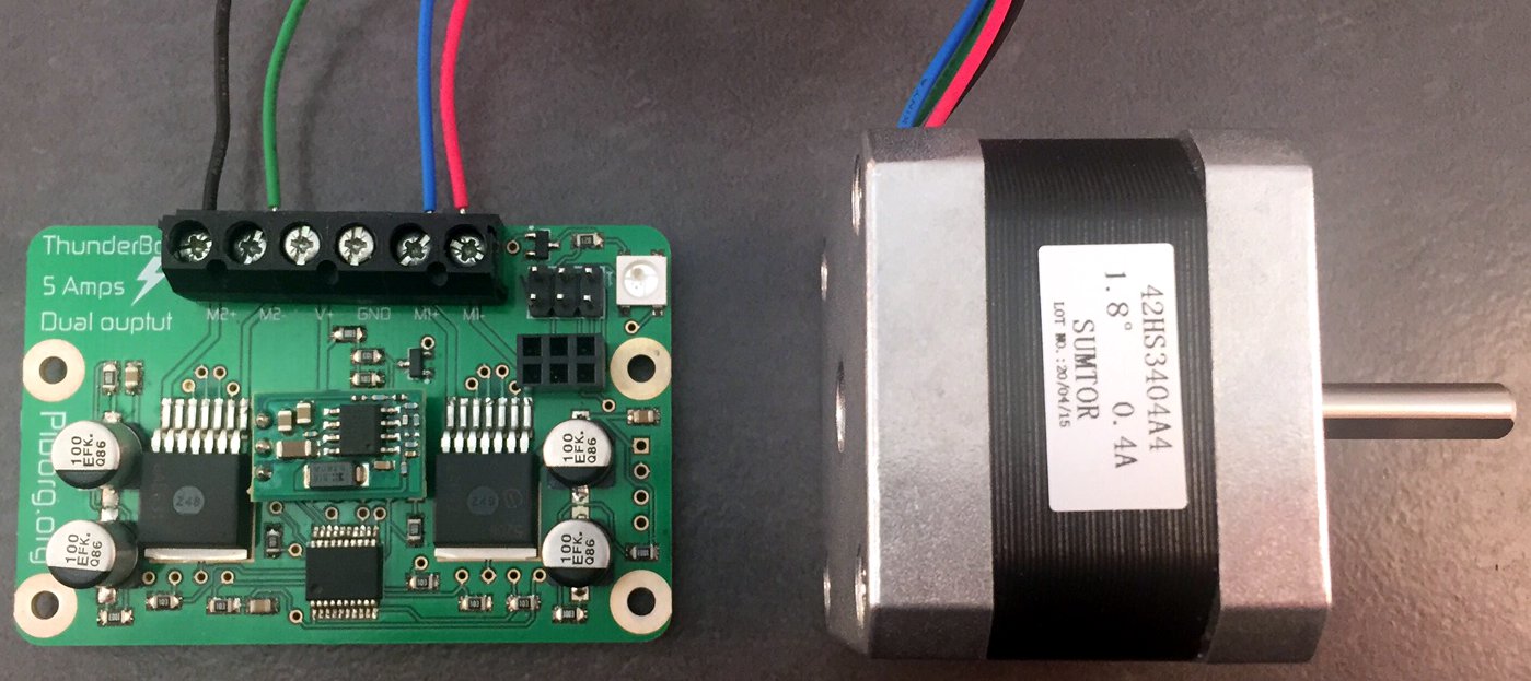
The shown stepper connection colours are based on the following internal wiring for the stepper:
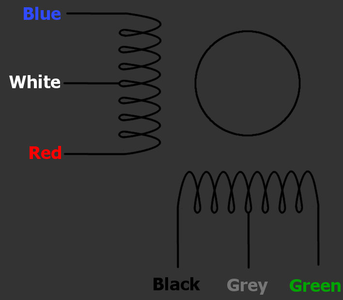
Note that on 5 / 6 wire steppers the remaining connections should be the center-taps (labelled white and grey above), these must not be connected to anything, we recommend putting some electrical tape over the end of these wires to ensure they do not contact any other connections.
Not all steppers will use the same wire colours, we recommend you check which wires are pairs in the stepper documentation or by using a multimeter.
RasPiO InsPiRing
All you need to do is connect the four InsPiRing connections onto the 5-hole connector from the back of the ThunderBorg like this: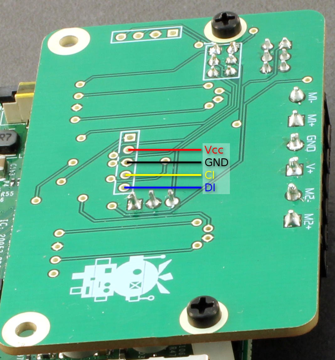
This is easiest to do without a ThunderBorg Lid fitted to the ThunderBorg, and to carefully solder wires onto these holes.
It is possible to solder to these holes from the top of the board, but it requires impressive soldering skills so we do not recommend it!
Software
Please note that this installation expects you to be connected to the internet, it will download i2c-tools and python-smbus for using I²C from Python, as well as pygame for the joystick examples and python-gtk2 for the LED examples.You probably need to enable I2C first, to do this:
- Enter the following command in a terminal:
sudo raspi-config - Move down to option
8 Advanced Optionsand press ENTER - Move down to option
A7 I2Cand press ENTER - Make sure
Yesis highlighted and press ENTER - When the dialog says I2C is enabled press ENTER
- Make sure
Yesis highlighted again and press ENTER - When the dialog says I2C will be loaded by default press ENTER
- Move right until
Finishis highlighted, then press ENTER
To run through the automatic installer just use this one line in a terminal:
bash <(curl https://www.piborg.org/install-thunderborg.txt)If you would prefer to manually run through the steps use the commands below:
mkdir ~/thunderborg
cd ~/thunderborg
wget http://www.piborg.org/downloads/thunderborg/examples.zip
unzip examples.zip
chmod +x install.sh
./install.sh
Manual download: http://www.piborg.org/downloads/thunderborg/examples.zip
At the end of the install a pair of desktop icon will appear for the example GUI, you should now be ready to go.
Multiple Boards
In order to setup multiple boards there is an additional step, we need to give each board a unique address.The allowable addresses are 3 (
0x03) to 119 (0x77), the numbers in parenthesis are in hexadecimal.The first task is to pick a unique number for each board, for this example we will have three boards which we will number 10, 11, and 12.
Start the Raspberry Pi with the first board
Open a terminal and start a Python prompt as follows:
cd ~/thunderborgpythonLoad the library
import ThunderBorgSet the address of the attached board, the function should tell you if this is successful or not
ThunderBorg.SetNewAddress(10)Disconnect the attached board and connect the next board, you can do this with the Raspberry Pi still running if careful, if you are worried shut the Raspberry Pi down first, then repeat the steps up to and including loading the library.
Set the address of the attached board, repeat the last two steps for each board.
ThunderBorg.SetNewAddress(11)ThunderBorg.SetNewAddress(12)Finally attach all of the boards at once, then run the following to see what addresses were found:
print ThunderBorg.ScanForThunderBorg()If everything went well the last line should show the numbers you set, e.g.
[10 11 12]You can now use them all in a script like so
# Setup the library ready for use
import ThunderBorg
# Board #1, address 10
TB1 = ThunderBorg.ThunderBorg()
TB1.i2cAddress = 10
TB1.Init()
TB1.ResetEpo()
# Board #2, address 11
TB2 = ThunderBorg.ThunderBorg()
TB2.i2cAddress = 11
TB2.Init()
TB2.ResetEpo()
# Board #3, address 12
TB3 = ThunderBorg.ThunderBorg()
TB3.i2cAddress = 12
TB3.Init()
TB3.ResetEpo()
Simply use
TB1, TB2, or TB3 anywhere you would have used TB in a single board example.You can use as many boards as there are free address numbers, over a hundred in all ^_^
General Usage
Example GUI
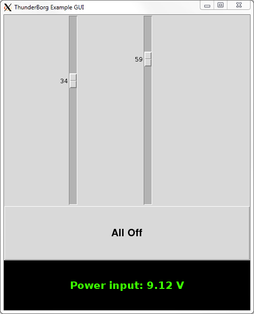
The All Off button stops both motors from moving.
At the bottom is the current voltage reading from the battery.
The colour of the reading should match the battery limit settings on the ThunderBorg. This can be run from the desktop shortcut, or from the ThunderBorg install folder (
cd ~/thunderborg) using:./tbGui.pyLED GUI
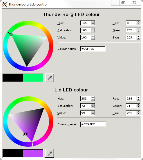
Moving the colour selection of the bottom wheel will change the colour of the ThunderBorg Lid LED if it is attached.
HTML colour codes can be entered into the "Colour name" box as well.
This can be run from the desktop shortcut, or from the ThunderBorg install folder (
cd ~/thunderborg) using:./tbLedGui.pyLED colours
When the ThunderBorg first starts it cycles the LED through red, green, then blue.After this it goes into battery monitoring mode, most of our examples also leave the LED in battery monitoring mode.
By default the colours are based on the limits of what ThunderBorg will use as a power supply:
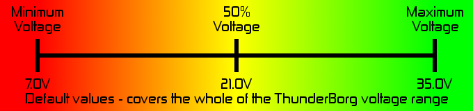
./tbSetBatteryLimits.py script and entering new levels.For a 9V rechargeable battery we find a range of 7.5 to 10.5 V works well:

For a 10x rechargeable AA battery pack we find a range of 9.5 to 13.5 V works well:

When the communications failsafe is enabled the LED is also used to indicate the failsafe has kicked in.
In this situation both LEDs will flash between yellow and red to indicate the board is no longer being talked to.
This will stop when the failsafe is disabled or the Pi starts communicating with the ThunderBorg regularly.
Other Examples
The following scripts may be run from the ThunderBorg install folder (cd ~/thunderborg):
./tbSequence.py - Runs both motors through a pattern of speeds../runTbJoy.sh - Uses a joystick to control both motors like a car (may require setup)../tbStepper.py - Controls a single stepper motor, asks user for commands../tbStepperSeq.py - Controls a single stepper motor, runs a looping pattern../tbLedWave.py - Makes both LEDs go through a soothing wave pattern../tbReadBattery.py - Reads the current battery level at a regular interval../tbExternalLedWave.py - Makes an InsPiRing go through a soothing wave pattern.For more information or setup help see the full example details here.
Python Library
The example scripts make use of our Python library,ThunderBorg.py, to command the board.The library exposes all of the features of the board with the following functions:
# Setup the library ready for use
import ThunderBorg                      # Load the library
TB = ThunderBorg.ThunderBorg()          # Create a board object
TB.Init()                               # Setup the board

# Setting motor speeds
TB.SetMotor1(power)                     # Set motor 1 speed
TB.SetMotor2(power)                     # Set motor 2 speed
TB.SetMotors(power)                     # Set speed of both motors
TB.MotorsOff()                          # Stop both motors

# Reading motor speeds
TB.GetMotor1()                          # Read motor 1 speed
TB.GetMotor2()                          # Read motor 2 speed

# Controlling the LED
TB.SetLed1(r, g, b)                     # Set the colour of the ThunderBorg LED (values from 0.0 to 1.0)
TB.GetLed1()                            # Read the colour of the ThunderBorg LED (values from 0.0 to 1.0)
TB.SetLed2(r, g, b)                     # Set the colour of the ThunderBorg Lid LED (values from 0.0 to 1.0)
TB.GetLed2()                            # Read the colour of the ThunderBorg Lid LED (values from 0.0 to 1.0)
TB.SetLeds(r, g, b)                     # Set the colour of both LEDs (values from 0.0 to 1.0)

# Battery monitoring
TB.SetLedShowBattery(enabled)           # Set if the LEDs reflect the current battery reading
TB.GetLedShowBattery()                  # Read if the LEDs reflect the current battery reading
TB.GetBatteryReading()                  # Read the current voltage level from the battery
TB.SetBatteryMonitoringLimits(min, max) # Set the limits for the LED based battery monitoring
TB.GetBatteryMonitoringLimits()         # Read the limits for the LED based battery monitoring

# Controlling the failsafe
TB.SetCommsFailsafe(enabled)            # Set if the communications failsafe is active
TB.GetCommsFailsafe()                   # Read if the communications failsafe is active

# Testing for faults
TB.GetDriveFault1()                     # See if there is a fault reported for M1
TB.GetDriveFault2()                     # See if there is a fault reported for M2

# RasPiO InsPiRing control
TB.SetExternalLedColours([[r,g,b], [r,g,b], [r,g,b], ..., [r,g,b]])
										# Set the colour of each LED on the InsPiRing (values from 0.0 to 1.0)

# Setting parameters (before Init)
TB.i2cAddress = address                 # Set the address of the board to use
TB.printFunction = function             # Re-route / disable diagnostic messages

# Reading parameters (after Init)
print TB.busNumber                      # Shows which I²C bus the board is connected on
print TB.foundChip                      # See if the board is found / not found

# Other functions
ThunderBorg.ScanForThunderBorg()        # Sweep the I²C bus for available boards
ThunderBorg.SetNewAddress(address)      # Configure the attached board with a new address
TB.Help()                               # Get help on the available functions
For more complete details see the ThunderBorg library reference.
To see the source code for the library or any of the examples see the code listings here.

