
4Borg - DiddyBorg's smaller brother
Step 1
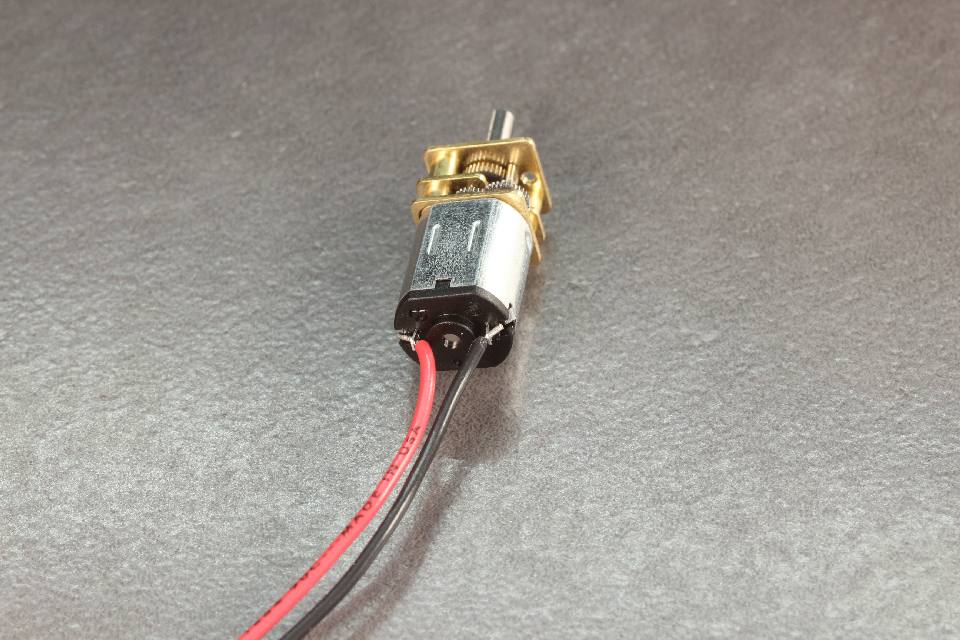 Solder the Red cable onto the + connector of a motor. To do this, place the cable through the hole and heat up both the cable and hole with the soldering iron, while adding solder. Solder the black cable onto the other connector. Trim the cable so the motor has 5.5" (14cm) of cable attached to them. Repeat this for ONE more motor. Pre soldered motors can be purchased for extra cost if you don't want to solder yourself.
Step 2
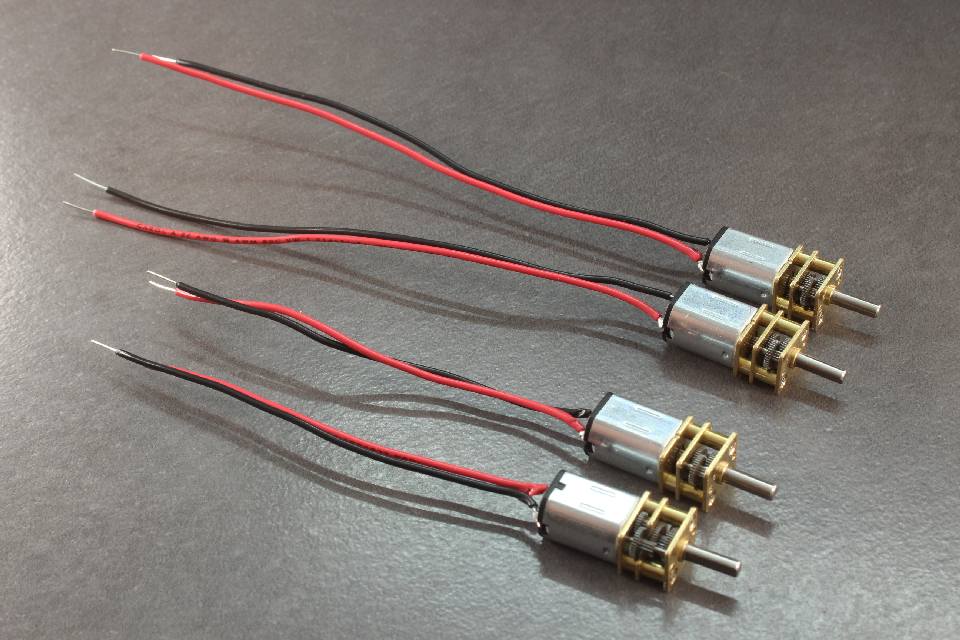 Solder to the he other two motors. These should have approx 4" (10cm) of cable attached to them.
Step 3
 Cut another three pairs of 4" (10cm)
Step 4
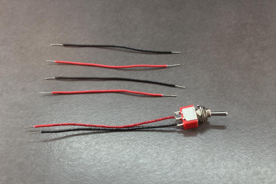
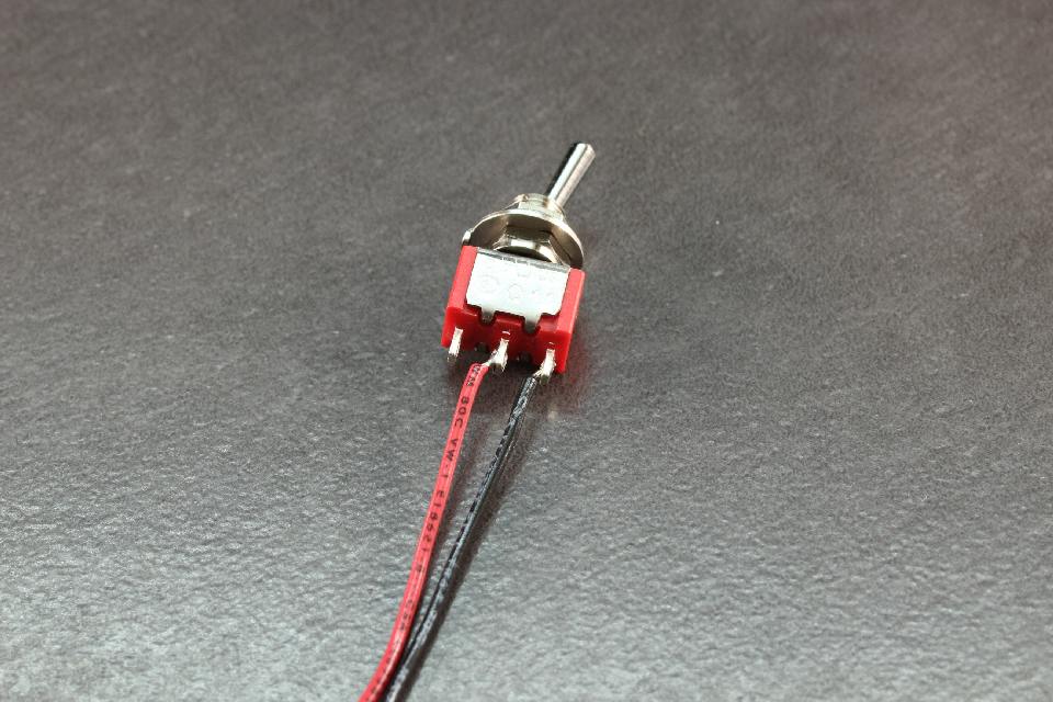 The switch cables should be soldered to the center connector and an edge connector on the switch.
Step 5
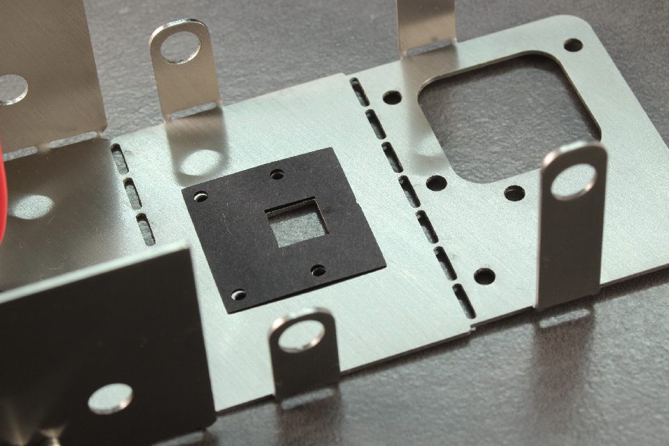
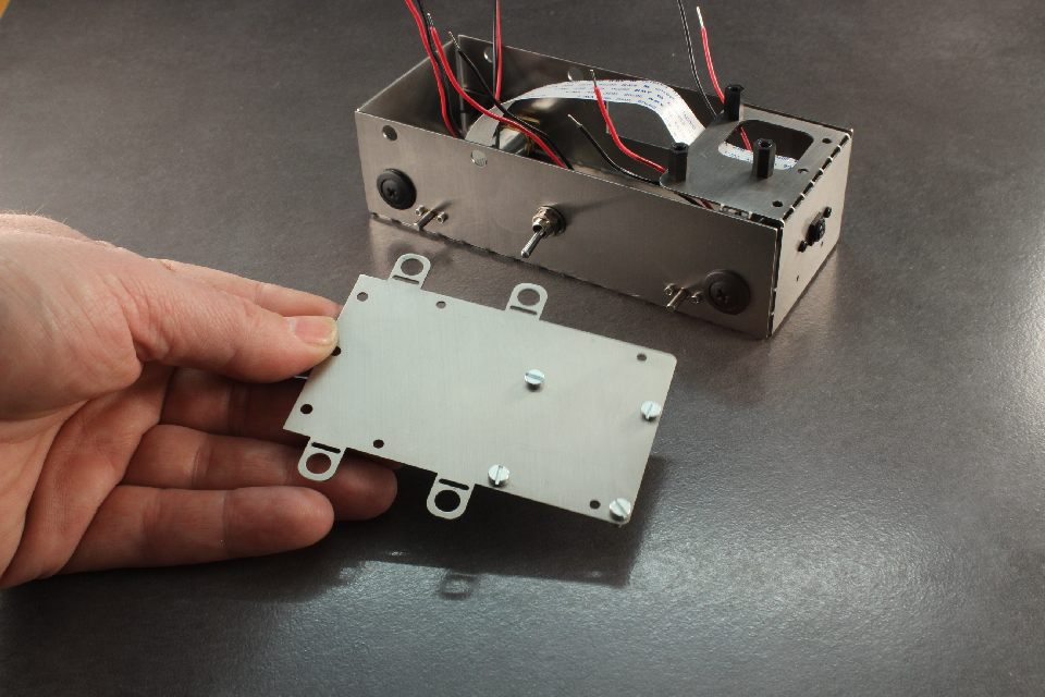
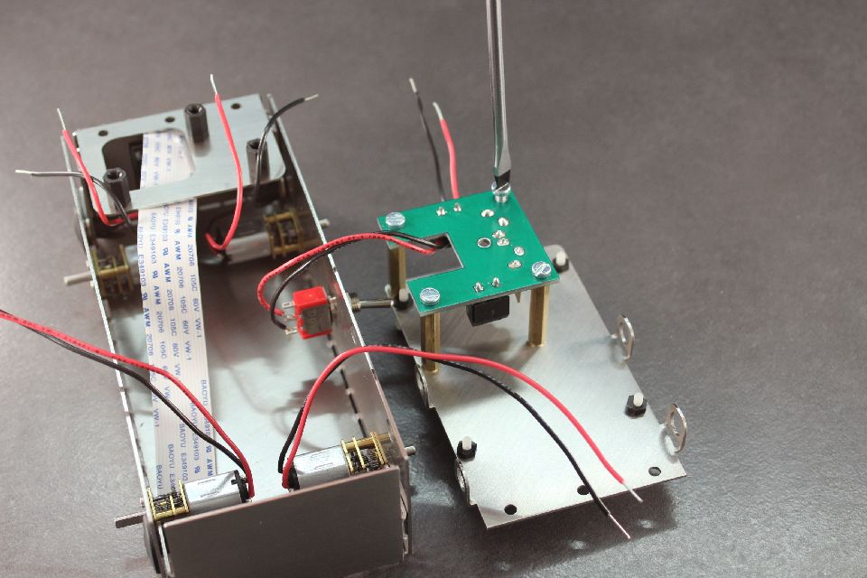
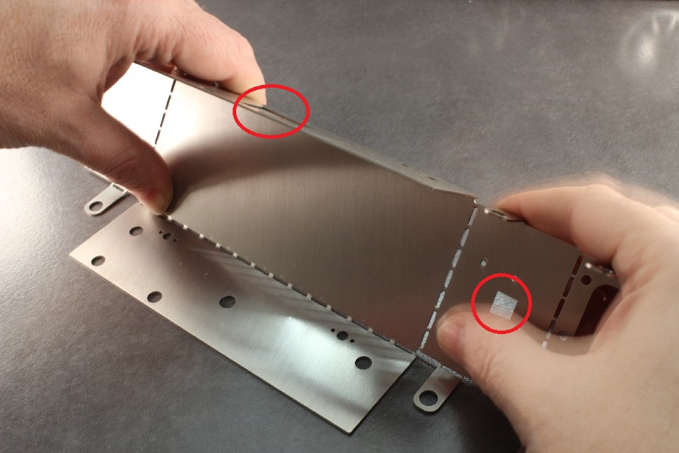 In a moment, we will bend the chassis, but before we do, make sure of the orientation the chassis as in this picture and the following picture. Taking note of the position of the rectangular cut outs (for camera and battery). These should be either at top and right as in this picture, or left and bottom as in the next picture.
The stainless steel should only be bent once. Repeated bending will cause it to break, and this will leave sharp exposed edges. Be certain which direction you need to bend the steel before doing so.
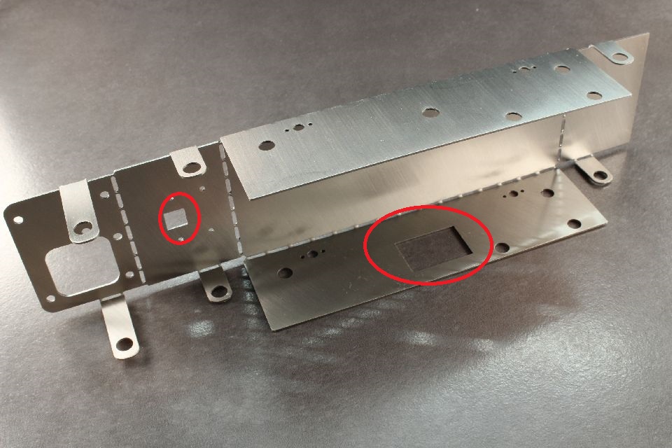
In a moment, we will bend the chassis, but before we do, make sure of the orientation the chassis as in this picture and the following picture. Taking note of the position of the rectangular cut outs (for camera and battery). These should be either at top and right as in this picture, or left and bottom as in the next picture.
The stainless steel should only be bent once. Repeated bending will cause it to break, and this will leave sharp exposed edges. Be certain which direction you need to bend the steel before doing so.
Step 6
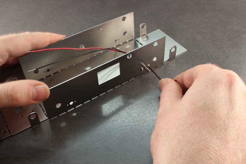
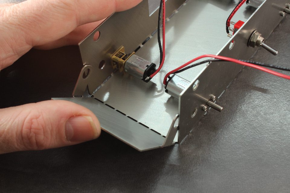
 Bend the sides of the chassis towards yourself as shown.
Step 7
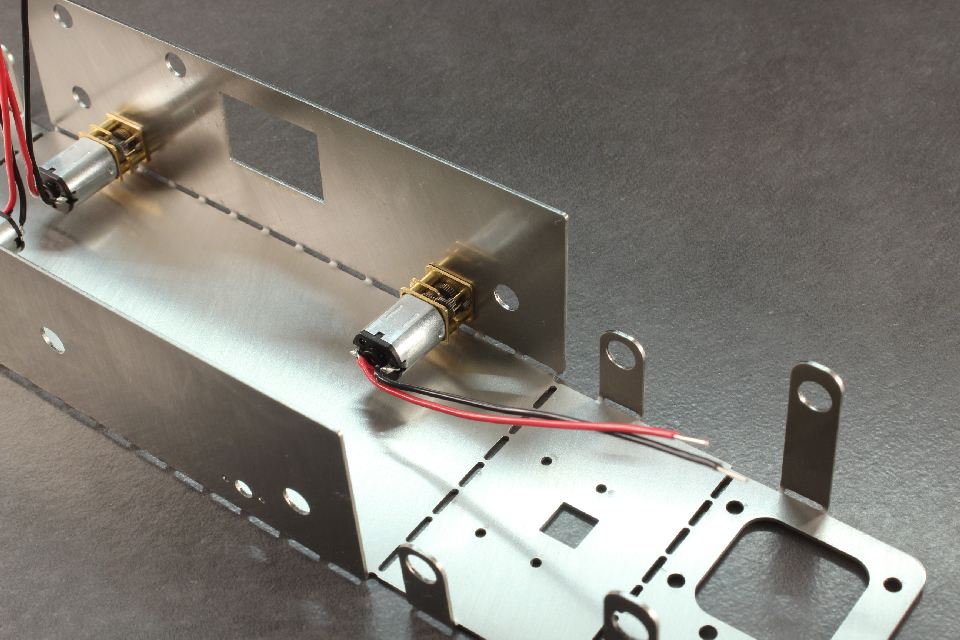
 Insert the motors with the long cable toward the back (furthest from the camera connection). Orient the motor through the hole, and with the small black allen key, gently tighten the M1.6x3 cap head screws. Do not do these up too tight as you can strip the thread in the motor.
Step 8
 Install all the motors as shown.
Step 9
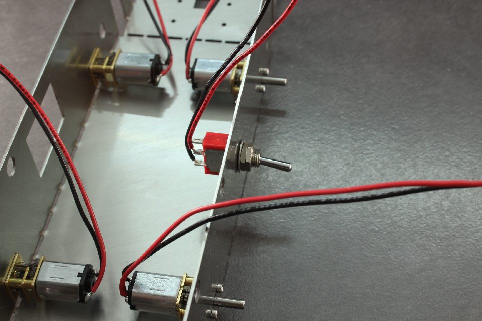
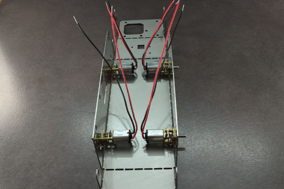 Orient the cables so it is obvious which side cable belongs to each motor.
Step 10
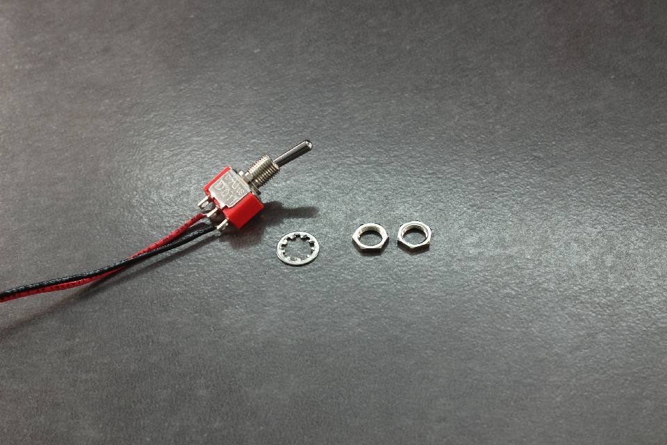 Remove all nuts and washers from the switch. We will discard the locating washer. Keep the two nuts and the toothed washer.
Step 11
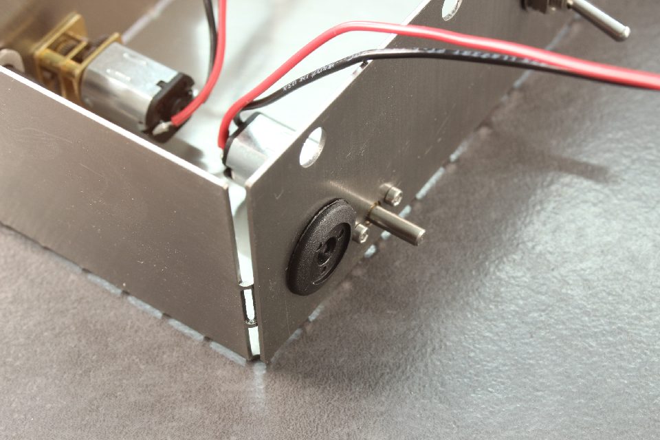
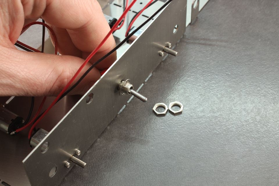 Insert the switch in the hole opposite the rectangular battery cutout. Place the toothed washer on first, followed by the two nuts.
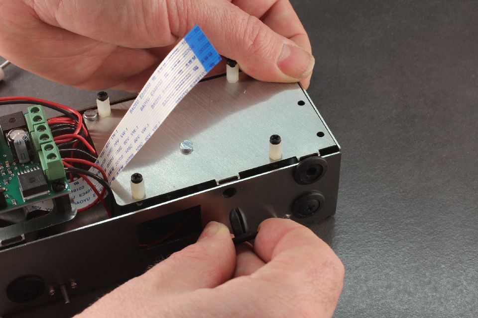
Step 12
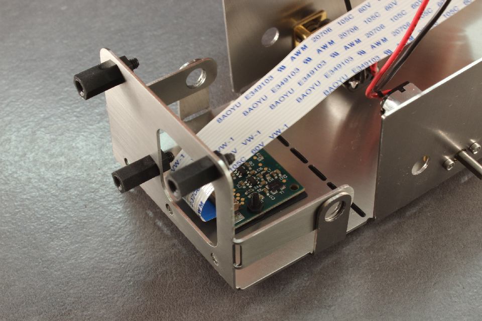
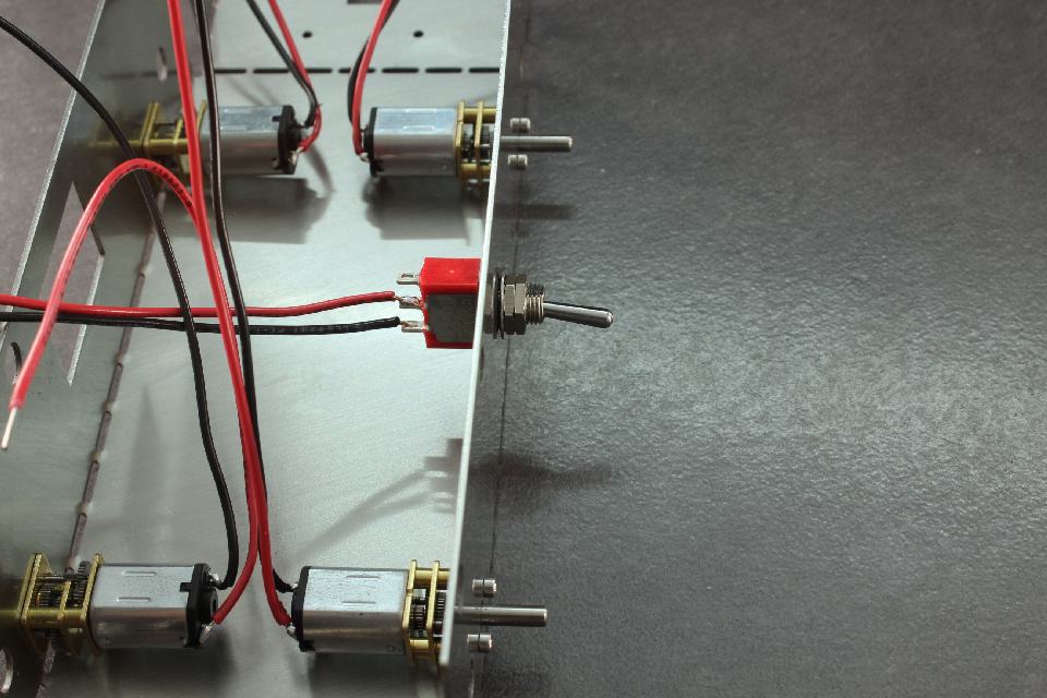 Before tightening, ensure the switch is in vertical configuration as per picture.
Step 13
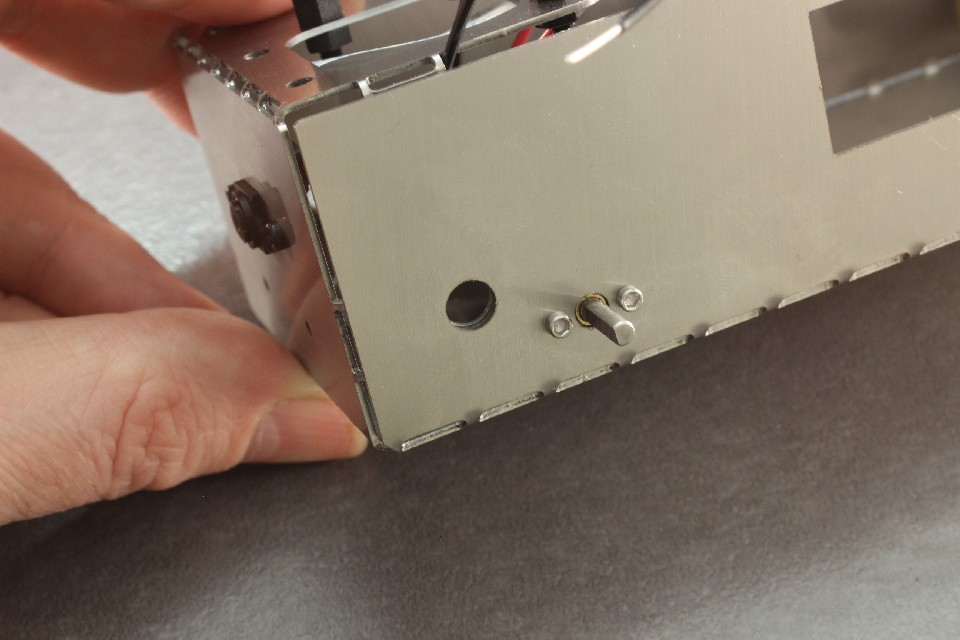
 Tighten nuts and bend cables so they go up and over the switch.
Step 14
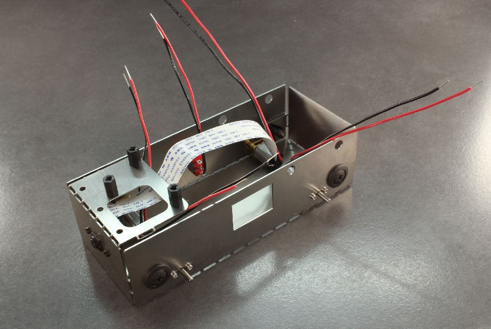
 Bend the tabs on the end pate to 90 degrees, and then bend the end plate up. The holes should meet.
Step 15
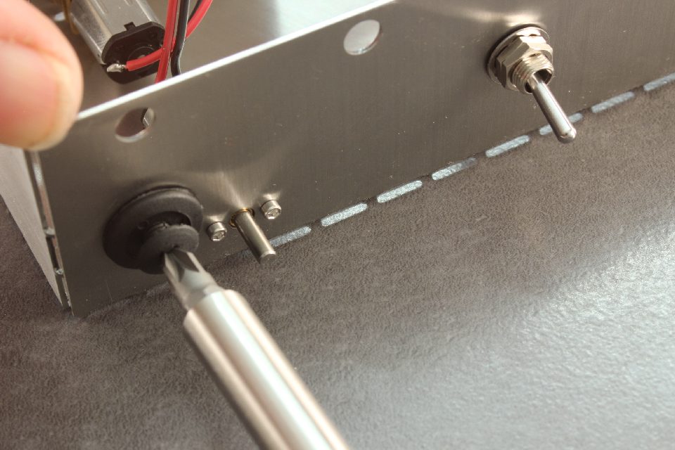
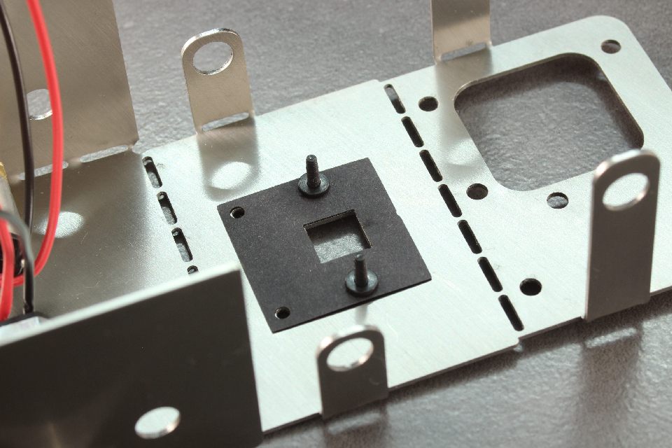
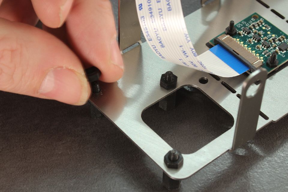
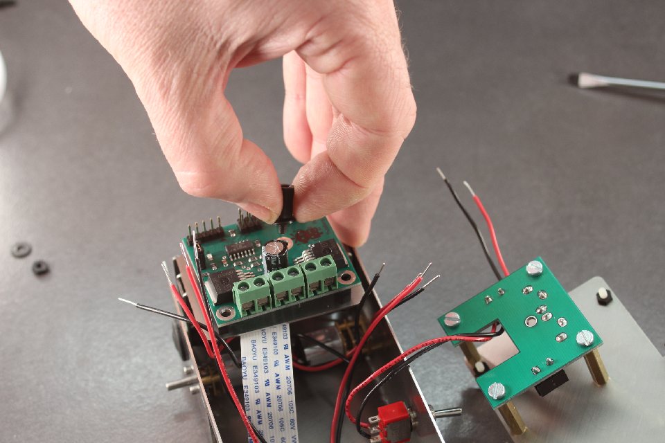
 Install the plastic clip into the hole. You may need to rotate this back and forth with pressure from your thumb in order to make sure it is completely flush.
Step 16
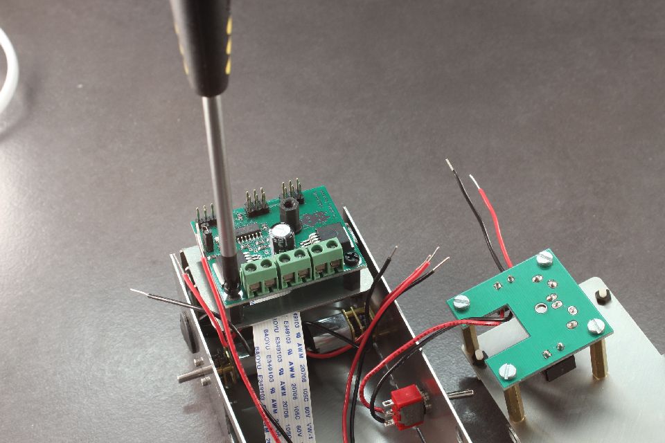
 Insert the plastic clip screw into the plastic clip. Repeat for both sides.
Step 17
 If using the camera, install the protective paper layer on the camera mount.
Step 18
 Install the two M2 screws and place the washers on the side closest to the paper.
Step 19
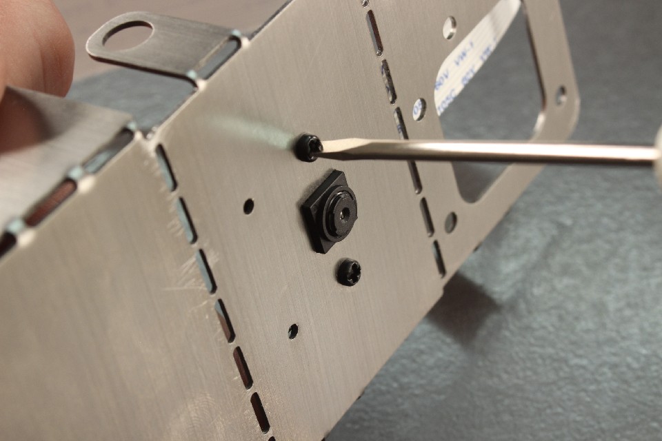 You will need a small screwdriver that fits the M2 screw head. Sometimes a small flat bladed will fit.
Step 20
 Place the camera over the screws, add the M2 black nylon nuts and tighten gently.
Step 21
 Add the M3x10 posts to the three end most holes. Use the M3 nylon nuts to secure them as shown.
Step 22
 Bend the end most piece at the fold line 90 degrees so that the long tab is inside of the shorter tab as shown.
Step 23
 Bend the next fold line 90 degrees and make sure all three holes align correctly.
Step 24
 Install the plastic clips into the holes as shown.
Step 25
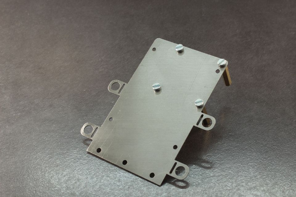
 Take 4x M3x6 cheese head screws and place them in the four holes of the second chassis piece as shown in the picture. Make sure that the orientation of the piece is as shown - that is the four holes to the right bottom.
Step 26
 Screw the cheese head screws into the M3x25 standoffs.
Step 27
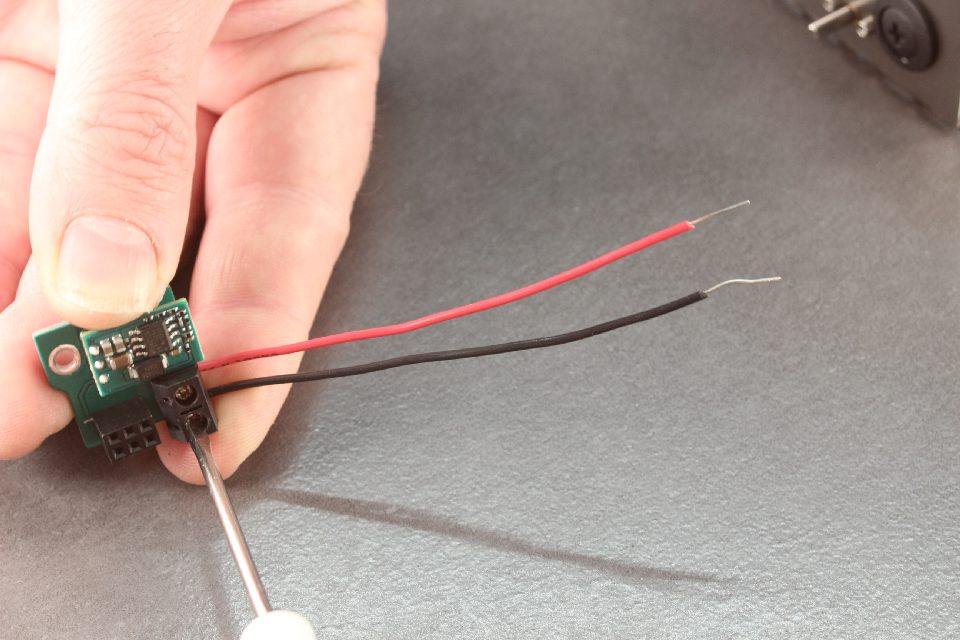
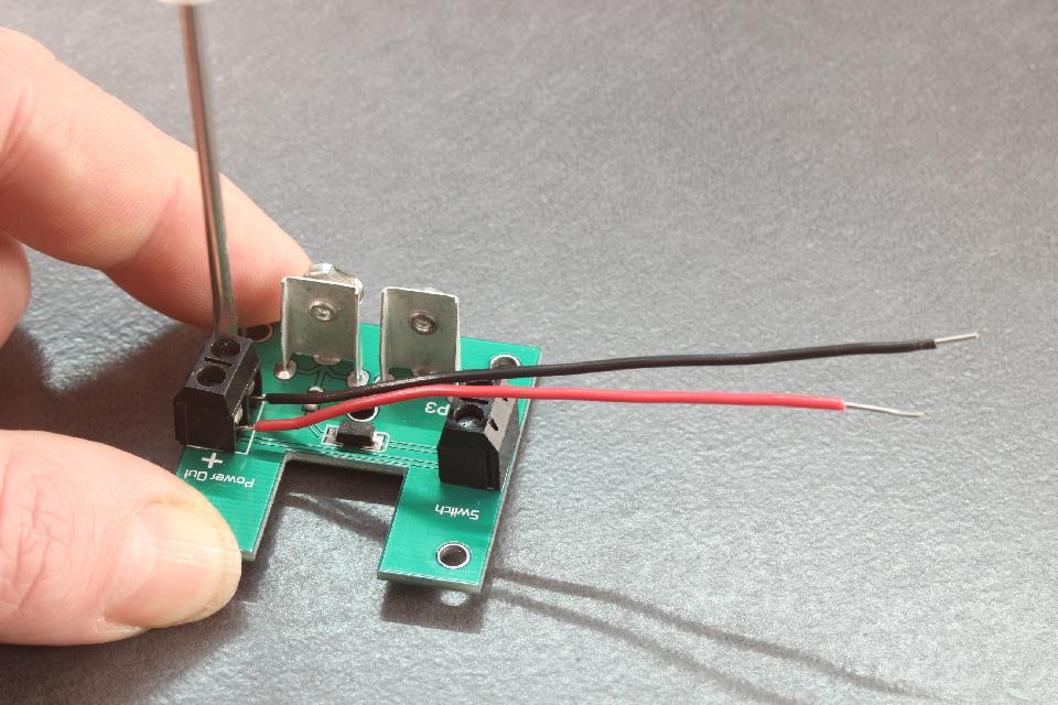 Take the battery board and screw two of the cables into the "power out". Make sure the red cable is connected to the side with the + symbol.
Step 28
 Put the switch cables into the switch side and tighten all cables.
Step 29
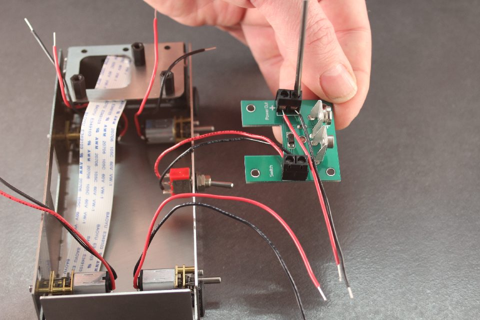
 Rotate the battery board and install it on to the top plate's M3x25 posts.
Insert the M2.5 white nylon posts into the 4 holes nearest to the battery board
Bend the 4 tabs up to 90 degrees.
Rotate the battery board and install it on to the top plate's M3x25 posts.
Insert the M2.5 white nylon posts into the 4 holes nearest to the battery board
Bend the 4 tabs up to 90 degrees.
Step 30
 Insert the PicoBorg Reverse onto the three nylon posts. Put an addition nylon post with a washer in the center hole.
Step 31
 Use nylon screws for the remaining two holes.
Step 32
 Screw the remaining cables into the BattBorg. Ensure the Red wire is on V+ and the Black wire is on GND.
Step 33
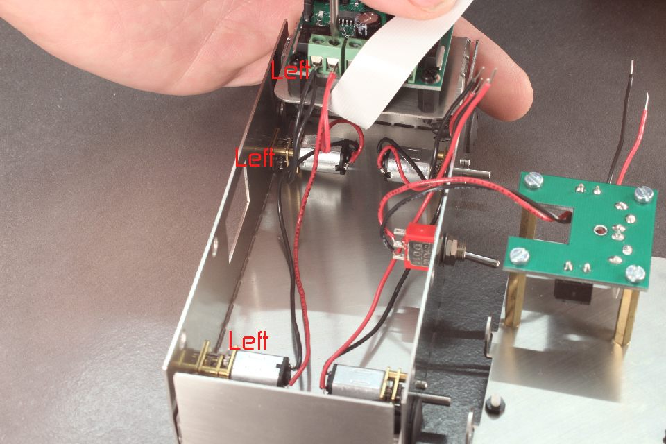 On the battery left hole side of the robot, connect both black cables from the motors which into M1- (leftmost connector when looking at connectors on PicoBorg Reverse).
On the same side, connect the two red cables from this side to the next left most connector (M1+).Be careful with the Raspberry Pi camera cable here, that it doesn't get damaged.
On the battery left hole side of the robot, connect both black cables from the motors which into M1- (leftmost connector when looking at connectors on PicoBorg Reverse).
On the same side, connect the two red cables from this side to the next left most connector (M1+).Be careful with the Raspberry Pi camera cable here, that it doesn't get damaged.
Step 34
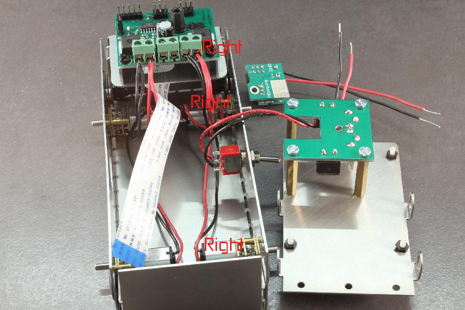 Connect the motors on the right switch side of the robot into M2- and M2+.
Step 35
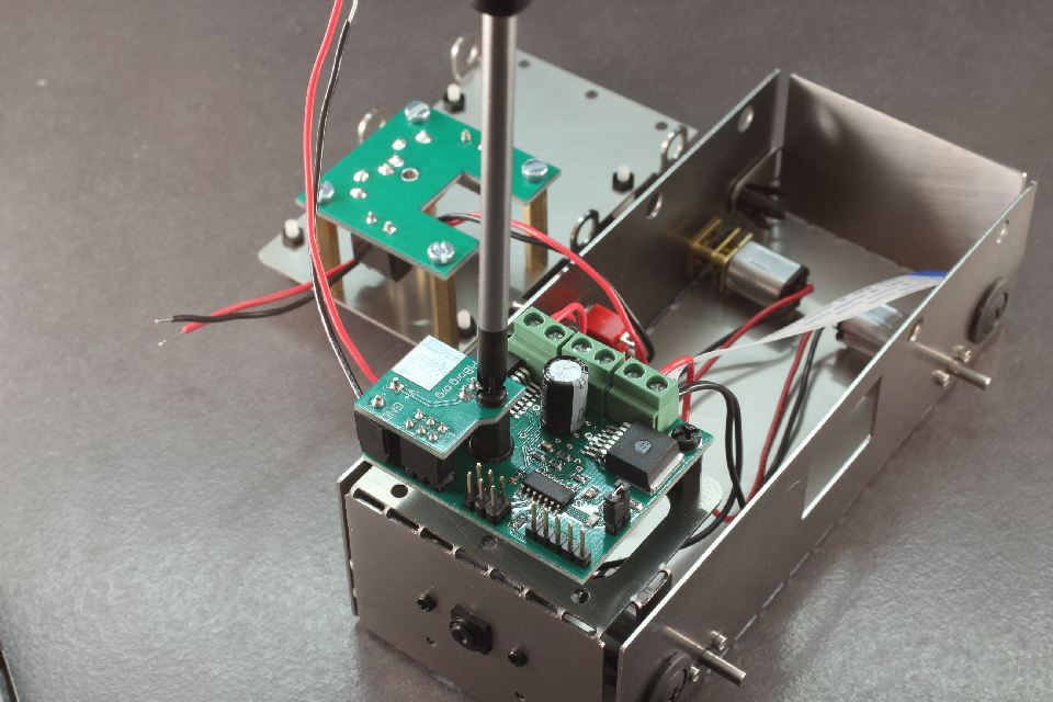 Install the BattBorg onto the PicoBorg Reverse and screw in the black M3 nylon screw.
Step 36
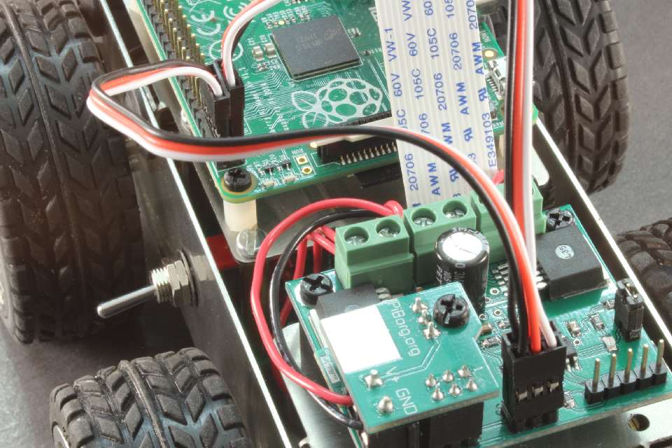
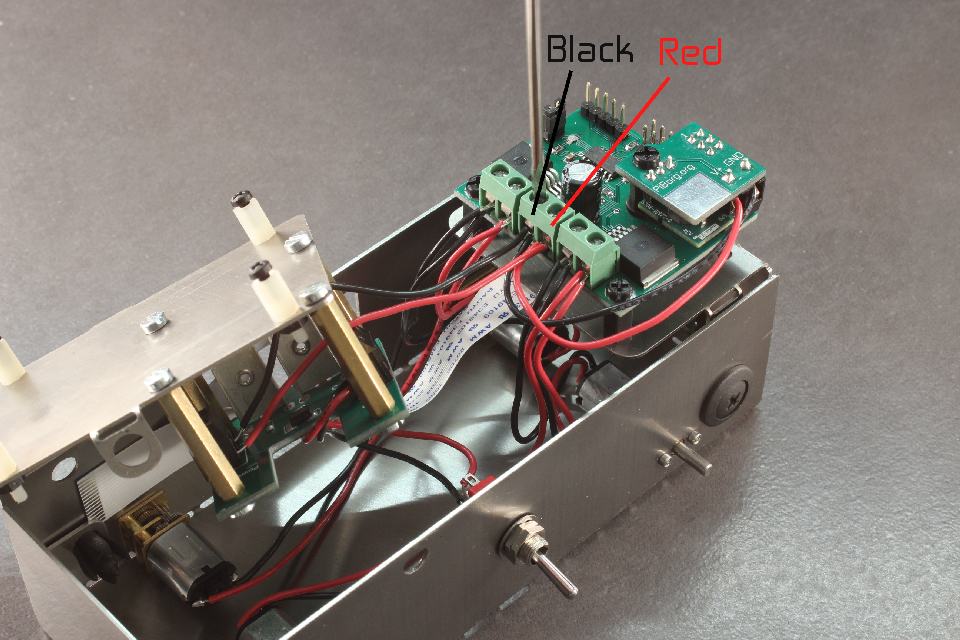 Run the power cables from the BattBorg V+ and GND, and from the battery connector board into the V+ and GND of the PicoBorg Reverse. Check the polarity is correct by looking carefully at the colours in this picture.
Step 37
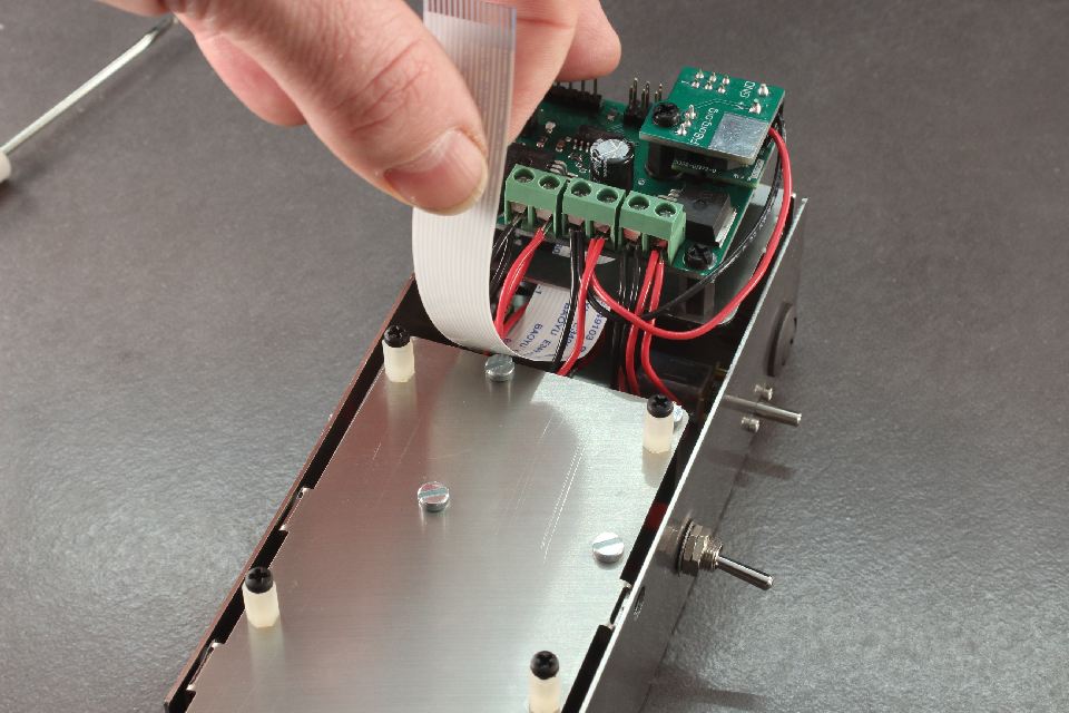 Carefully lift the camera cable out of the way, and install the top plate.
Step 38
 Install the plastic clips to hold the top plate on.
Step 39
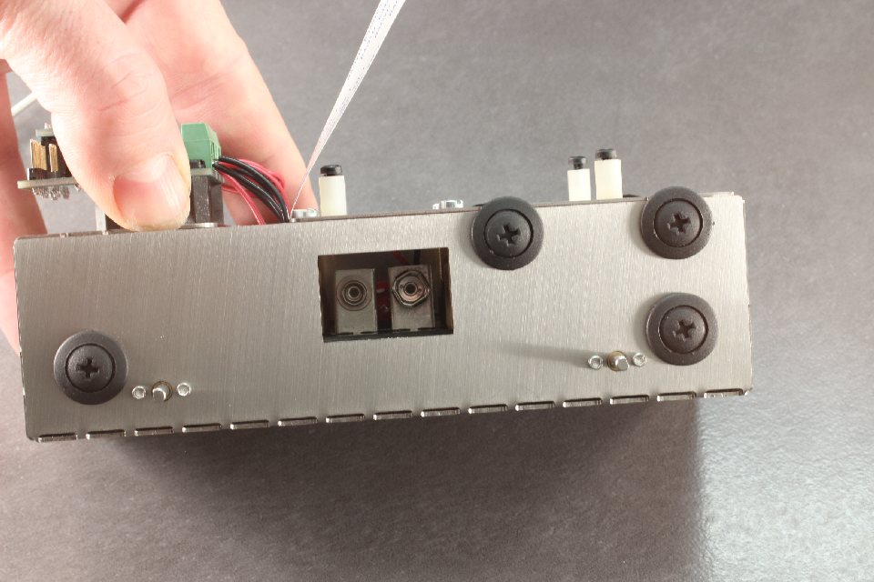 Make sure there is no cable obstructing the battery contacts.
Step 40
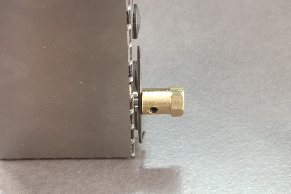 Insert the grub screws into the hubs and locate them on the motor shafts. A good rule is to use the thickness of the small allen key above the M1.6x3 cap screw to get the distance as in the picture.
Step 41
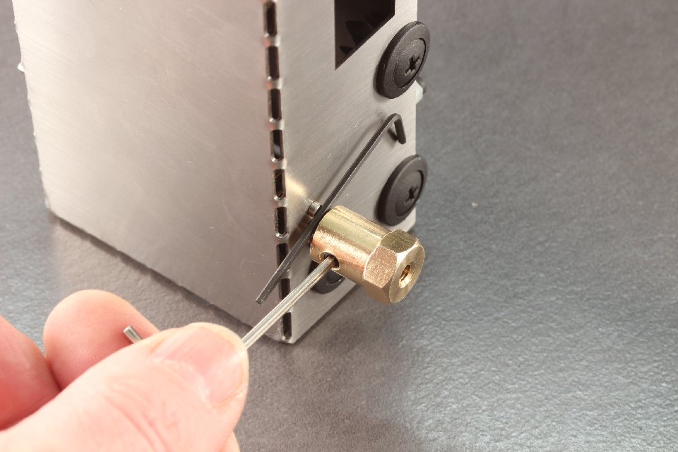
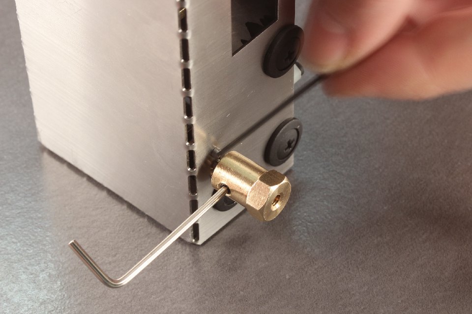 The small allen key should be able to freely move between the hub and the head of the M1.6x3 cap screw
Step 42
 When happy with position, locate and tighten both sides equally.
Step 43
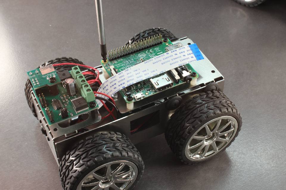
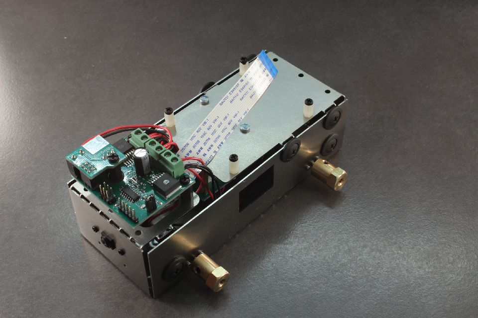 Our 4Borg should look like this.
Step 44
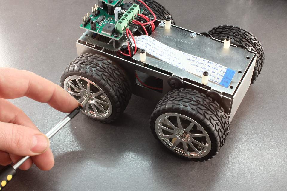 Put the wheels on the hubs, and insert and tighten the M4 screws.
Step 45
 Insert the Raspberry Pi, and tighten in the M2.5 nylon screws.
Step 46
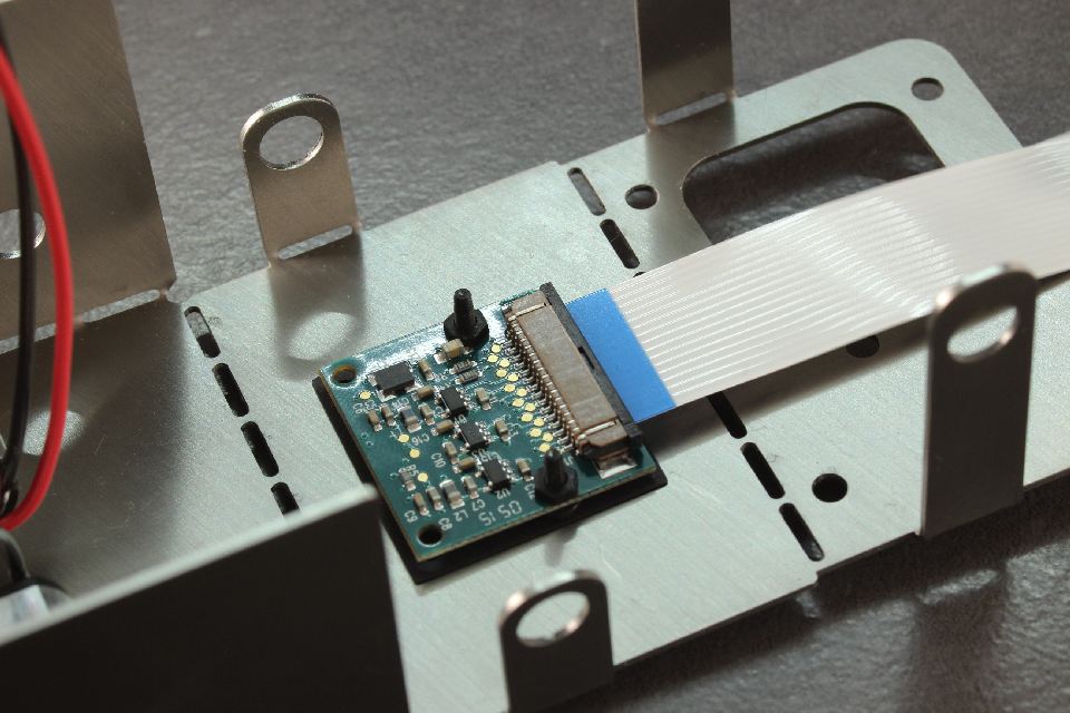
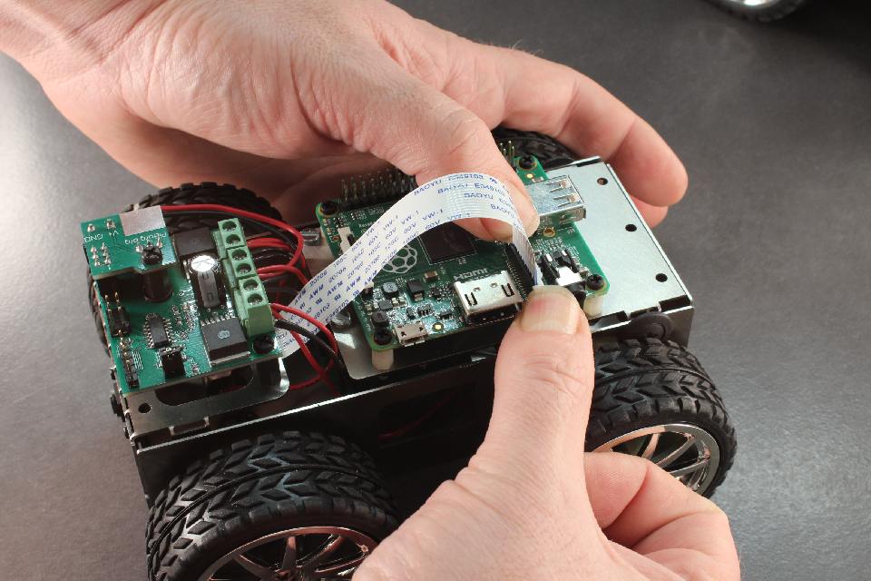 If using the camera, open the camera connector, feed in the ribbon cable and gently press down on both sides to lock in the ribbon.
Step 47
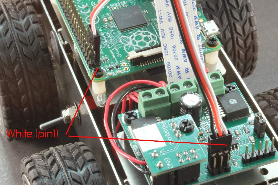 Place one of the 3 pin cables on Pin1 on the PicoBorg Reverse, and Pin1 on the Raspberry Pi. Use white as Pin1 on both sides. Check diagram against your robot to make sure this is correct.
Step 48
 Install the other 3 pin cable, this time white to pin2 as per diagram.
Step 49
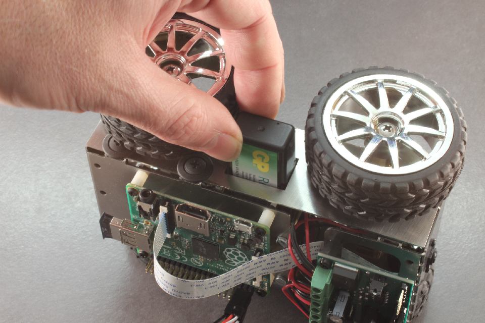 Install battery. Make sure you have the battery the correct way around by looking at the battery contacts. The negative of the battery goes towards the camera (front) of the robot.
Note on batteries. You will need a good freshly charged battery. We recommend using GP ReCyKo 8.4V batteries. A full charge should last between 10-30 minutes depending on the hardware and software load you give the robot.
Now switch on the robot and the Pi should boot up. Please click the getting started tab to install the software.

