
Installation Issues

Forums:
Post here for queries regarding setup problems.
We recommend you try using the troubleshooting instructions here first if you have not already.
Please try to list as much about the problem as you can (OS distribution, versions, motor setup et cetera), the more we know the easier it is to help :)
- Log in to post comments


jg
Tue, 08/08/2017 - 04:51
Permalink
Autostarting Python scripts that use pygame
Have just fired up my diy monsterborg, and having lots of fun.
I would like to autorun tbJoystick.py using systemd, but it seems that any python code that uses pygame requires a GUI, so if autostarted or started from a terminal is destined to crash with a "pygame.error: video system not initialized". I guess the only answer is to use a different joystick interface. Does anyone have a solution?
piborg
Tue, 08/08/2017 - 11:36
Permalink
pygame.error: video system not initialized
We have seen this issue before, the problem is an issue with pygame trying to create a GUI the script does not need.
Put simply the script tries to tell pygame that it does not need the window with these lines:
The last of these three lines should be necessary, but on most Raspberry Pis it seems to cause an error instead. Try removing the comment symbol (
#) at the start of the line:and see if the script will now start from a terminal correctly. If it does it should also work when autostarted :)
jg
Tue, 08/15/2017 - 03:28
Permalink
Thanks for the prompt reply.
Thanks for the prompt reply.
Unfortunately uncommenting line 77 of tbJoystick.py causes this error "pygame.error: Unable to open a console terminal" on my system.
WORKAROUND
Uncomment line 77 of tbJoystick.py and run from terminal as root.
eg. sudo ./tbJoystick.py
This allows tbJoystick.py to be run successfully from a terminal, but I still cannot run it from systemd.
piborg
Tue, 08/08/2017 - 16:56
Permalink
Start with the desktop loading
What you can do is try to get the graphical desktop to start the script instead.
There is a good guide about doing this here: http://www.raspberry-projects.com/pi/pi-operating-systems/raspbian/auto-...
xwox
Sat, 09/09/2017 - 18:14
Permalink
Installation instructions?
Hi,
my MonsterBorg just arrived this morning.
1) I am wondering where I can find some mechanical/electrical installation instructions.
2) Where can I find the SW installation manual?
Thx for your answers in advance.
Regards,
Joerg
piborg
Sun, 09/10/2017 - 13:25
Permalink
Building MonsterBorg
All of the instructions are up on this website.
We recommend you install the software first: software install instructions.
Once that is done proceed to the build instructions.
Stigmaru
Wed, 06/26/2019 - 18:21
Permalink
This page is gone. It has a
This page is gone. It has a 404 error message. Where else can we get the software installation instructions?
https://www.piborg.org/monsterborg/install
piborg
Wed, 06/26/2019 - 18:46
Permalink
MonsterBorg setup instructions
You can find the MonsterBorg setup instructions at https://www.piborg.org/blog/monsterborg-getting-started
We have recently moved the website to a new server and a few of the links still need to be fixed :)
theborg
Wed, 09/13/2017 - 19:06
Permalink
I'm gettingpi@PiBot:~
I'm getting
pi@PiBot:~/monsterborg $ sudo python monsterWeb.py
Traceback (most recent call last):
File "monsterWeb.py", line 15, in
import cv2
ImportError: No module named cv2
when running the web code. Before I start troubleshooting it more, have you tried the code with the "lite" (for example no GUI desktop) installation of Raspbian, since that's what I always install by default? Maybe it's missing the CV2 module. Or should it have been installed when I ran the installation script?
I did get this message
sudo: easy_install: command not found
when I ran the installation, but it finished OK otherwise.
piborg
Thu, 09/14/2017 - 11:35
Permalink
Installing the camera
There are some extra bits of software you will want for talking to the Pi Camera:
You should be able to fix the
easy_installerror by installing it first:Everything should work fine with Raspbian Lite, the code itself has been tested. We are only using
easy_installto setuppygame, on recent versions of Raspbianpygameis already installed so the step is usually unnecessary.bleimy
Fri, 07/14/2023 - 15:03
Permalink
Same problem
I could not get this working. I did a clean install, following all instructions. But there is some problem with cv2 not being imported in python 2. It is installed but only for python 3. It would fantastic if someone with a working system (piborg + Rpi + camera) could just create an image and provide it here for others. It would save so much pfaffing about...
Barring that, can someone explain how we can get the scripts to work?
piborg
Fri, 07/14/2023 - 15:45
Permalink
Updated to Python 3
The good news is that this is not a problem, the current MonsterBorg scripts on our website are setup for Python 3 now :)
If you just installed the scripts using this command you should already have the Python 3 scripts:
You can check if you have the right version of the scripts by opening one of them in a text editor, e.g.
The new Python 3 copies start with:
The old Python 2 copies have this instead:
bleimy
Sat, 07/15/2023 - 07:57
Permalink
minor addendum
It all works now with kind help received about python3 adaptation. One other note - it is necessary to make sure to disable legacy camera support in raspi-config.
theborg
Wed, 09/13/2017 - 21:29
Permalink
Well that was fun while it
Well that was fun while it lasted, which was about 10 meters. I made a cable with a 9V connector on one end and LiPo battery connector on another. "Made sure" of the right polarity by comparing the 9V connector to a 9V battery and soldered it on... Nothing happened when I connected the LiPo and it was only after that when I realised the polarity was wrong since I compared it to a power source while the 9V connector on the Monsterborg is of course the one being powered. Switched it off after one second since the lights didn't come one but apparently that was enough, nothing happens anymore. Pi still works though.
What should I do? Are the motors fried as well?
piborg
Thu, 09/14/2017 - 11:28
Permalink
Good news and bad news
Well the good news is that the motors are almost certainly fine. Even if they did get powered they should not have exceeded any electrical limits.
The bad news is that the ThunderBorg is almost certainly dead, most of the components do not like being reverse powered :( It is possible the the Raspberry Pi has taken some damage to the GPIO pins even if it does power up, but it may have escaped without problem as well.
It is fairly likely that everything will be fine if you replace the ThunderBorg with a new one. You can order them from our shop here.
On a side note it may be easier to connect your LiPo to the V+ and GND screw terminals on the ThunderBorg instead of the 9V connector. This should reduce the chances of making a polarity mistake on the 9V connector, but it does prevent the power switch from working.
theborg
Tue, 09/19/2017 - 17:32
Permalink
Already ordered a new
Already ordered a new Thunderborg but decided to see if the old one could be revived and this is what I discovered:
- only the DCDC converter was dead. I soldered it off and replaced it with another converter. This one has to be connected by jumper cables as it's too big to be fitted like the original. One could also use the exact same part by ordering it from the shop.
- the battery lid was damaged as it no longer provides power to the Thunderborg
- my Pi 3 took some damage as well: while it powers on and seems to work as expected, it fails the GPIO test mentioned here. The test reports one SPI pin as damaged. I'm hoping this won't be a problem as I'm not using it.
So now I have a spare Thunderborg with reverse-polarity protection :P
While totally my own fault, I think it's a bit too easy to get the 9V connector polarity reversed, which can lead to an instant damage of almost 100€ (Thunderborg + Pi 3). The connector doesn't have + and - signs and is not protected from user error by having a connector shape that allows wrong polarity contact. Combined with no reverse-polarity protection, it's a risky combination in a learning platform which I imagine the Thunderborg/Monsterborg to be. Just something to think about :)
pmodiano
Thu, 09/14/2017 - 23:50
Permalink
monsterWeb.py fails
I just assembled my MonsterBorg and used the installers provided. When monsterWeb.py is executed, I get the following result:
$ Loading ThunderBorg on bus 1, address 15
Traceback (most recent call last):
File "/home/pi/monsterborg/monsterWeb.py". line 39, in
TB.Init()
File "/home/pi/monsterborg/monsterWeb.py", line 301, in Init
self.i2cRead = io.open("/dev/i2c-" + str(self.busNumber), "rb", buffering = 0)
IOError: [Errno 2} No such file or directory: ' /dev/i2c-1'
Any ideas?
piborg
Fri, 09/15/2017 - 11:22
Permalink
I2C might not be enabled
It sounds like I2C is not enabled or has a different name on your Pi.
First I would check I2C is setup in raspi-config. You can do this by:
sudo raspi-config5 Interfacing Optionsand press ENTERP5 I2Cand press ENTERYesis highlighted and press ENTERFinishis highlighted, then press ENTERAfter that re-run the ThunderBorg install script:
Hopefully the script will now be working correctly. If not run this command:
and post the results so we can take a look :)
pmodiano
Fri, 09/15/2017 - 12:43
Permalink
Thank you so much! That got
Thank you so much! That got me to the next level. Now it is failing when trying to initialize the camera. I know that the camera has been enabled so I am hoping that it is a simple matter of the ribbon cable having been partially pulled out. Of course, I will need to open it up to see.
I will be sure to post my progress.
Thanks again!
pmodiano
Tue, 09/19/2017 - 17:45
Permalink
Limited slip differential like functionality?
Avoiding left-left/right/right slippage
I got my monsterborg working to my delight. One thing I noticed is that when I was using it outside off-road, if you will, if for example the terrain was uneven and the left front wheel made contact with the ground but the left back wheel was in the air, because the motors are connected in parallel, almost no torque would be sent to the left front wheel and the left back wheel would just spin. This is similar to the way automotive differentials behaved prior to the introduction of the limited-slip differential.
So the question is this: How might one go about creating the equivalent of a limited-slip differential for the Monsterborg?
piborg
Wed, 09/20/2017 - 09:44
Permalink
How motors connected in parallel get their power
This is a tricky question to answer, but put simply it basically does already.
I will try and explain by describing what happens in the situation where the front left wheel is on the ground and the rear left wheel is in the air.
The first thing to know is that both motors are connected in parallel. This means at 100 % power both the front left and rear left motors have the full 12 V from the battery provided. The current given to each motor depends on the resistance of the motor and the voltage. The total power (torque and speed) comes from the voltage and current multiplied together, giving a wattage.
The motors actually have the lowest resistance when the are completely stationary. In other words they draw more current when stopped compared to when they are moving. As the motor turns faster the resistance increases, lowering the current drawn by the motor. This is why the motors have a natural maximum speed when they are not attached to anything, they get to the point that the motor is not getting enough power to increase speed.
So to sum up the last two paragraphs the slower a motor is going the more current it draws from the battery. At the same time both motors must be at the same voltage because they are connected in parallel. Finally the power to each motor is equal to the voltage provided multiplied by the amount of current it is drawing.
So for our example:
This means the current to the front left motor will be much higher than the rear left. In turn as the voltages are the same this means the total wattage to the front left motor is higher than the rear left motor.
Since the power (wattage) is split between speed and torque what actually happens is that the front left motor has a large increase in torque compared the rear left motor, allowing it to keep turning :)
On a side note this is why it is not a good idea to connect motors in series. If you did that the voltage is split unevenly between the motors based on their resistance. In that case the free-wheeling motor would take nearly all of the power and the other one would not turn at all!
Hopefully that clears things up a bit :)
marph
Tue, 09/26/2017 - 16:42
Permalink
Failed reading the drive fault state for motor #1!
Hi PiBorg support
I'm running into a weird problem:
I have 2 ThunderBorg boards connected to my Pi. On the first board there are 2 motors connected and on the second one, one motor is connected.
Now at first I can get all 3 motors to act as expected, but after using the single motor of the second board for some time (in both running directions) the python script starts to print these messages:
Failed reading the drive fault state for motor #1!andFailed reading the drive fault state for motor #2!.At first only some lines like that are printed and suddenly the script seems to end up in an endless loop and doesn't stop printing these lines until it's killed.
Additionally the first board starts to flash its LED red and yellow and doesn't work anymore. It doesn't help if I use the command
TB1.SetCommsFailsafe(False), only cutting the power of the board makes it work again.So what's the problem here? How can I make it work?
Thanks a lot in advance for help and best regards.
Simon
piborg
Wed, 09/27/2017 - 10:57
Permalink
Loss of communications
It sounds like the I2C signals are getting messed up at some stage and no longer get through. I2C connections can be difficult to debug so this make take a few tries to fix.
My first thought is that if you are running from batteries they may be getting low after the long run with the motor. This might be causing the 5V signal to the Pi to dip a bit low and in turn upset the I2C signals. If you are using a power supply make sure it has a high enough current rating to cope with all of the motors, power surges to all of the motors (stall currents), and powering the Raspberry Pi.
My second thought would be cabling, all of the following may help:
I would check the supply first as it is the more likely issue and is easier to fix / change.
marph
Mon, 10/02/2017 - 09:01
Permalink
Found and fixed the problem
Thanks a lot for the detailed hint! It helped me to find the problem :-) .
It was indeed a lack of shielding and I could fix it by using tin foil. The reason I have this height amount of noise, is a small old and cheap motor, which has to bear overvoltage.
maximus
Thu, 10/26/2017 - 12:03
Permalink
Hi PiBorg
Hi PiBorg
I have built and setup the Monsterborg using a pizero w as per the instructions provided in your guides.
I can manually control the motors using the Gui app on the desktop and the camera test you suggested shows the correct picture ( after open CV was installed )
the issue is that running the monsterWeb.py results in a hard crash of the zero everytime.
the script starts up ok and initiates the webserver and camera but then after about 30 seconds the crash happens.crashes (screen shows alternate red yellow lines, no response to keyboard or SSL terminal )
any ideas to troubleshoot and have you tried the monsterWeb.py code on a "zero W"
many thanks Max
piborg
Thu, 10/26/2017 - 12:08
Permalink
Using a Pi Zero W
We have not tested the
monsterWeb.pyscript on a Pi Zero W, however we have tested theyetiWeb.pyscript which is extremely similar.In either case the script should not be able to cause such a crash on its own, there is probably something else involved.
Is the MonsterBorg moving when the Pi crashes, or is it stationary?
maximus
Wed, 11/15/2017 - 10:48
Permalink
Hi Piborg, apologies for the
Hi Piborg, apologies for the delay getting back to you, have been away for a few weeks to get some sun !
the monsterborg is not moving its connected to a monitor via a mini to normal Hdmi cable and via a otg connector to a keyboard to the pi zero as well as usb power.
i tried with the battery pack into thunderborg controller and the result seems the same, if you can suggest a way to help me try to log whats happening im happy to share, but as it seems to be a hard crash of the pi im not sure how to recover the log before Poweroff/reset
piborg
Wed, 11/15/2017 - 14:11
Permalink
Diagnosing crashes
This can be tricky, there is not really a good simple way in this case. Hopefully some questions will shed more light on the problem.
marph
Mon, 12/04/2017 - 11:08
Permalink
ThunderBorg and Enviro pHAT
Hi there
I have the following configuration: 2 thunderborgs and an Enviro pHAT from Pimoroni all attached to the same Raspberry Pi.
Now to avoid any conflicts with I2C I watched out that the ThunderBorgs don't use any of the I2C addresses used by the Enviro pHAT (https://de.pinout.xyz/pinout/enviro_phat).
ThunderBorg.ScanForThunderBorg()tells me that they are using 0B and 0C, so there should be no conflict, but nevertheless ThunderBorg throwsFailed reading the drive fault state for motor #2!andFailed reading the drive fault state for motor #1!all the time, although the ThunderBorgs and the Enviro pHAT are working as expected.So my question: Why do the ThunderBorgs throw these errors and how can I avoid it?
Thanks a lot in advance.
piborg
Mon, 12/04/2017 - 12:16
Permalink
Have you set the correct addresses?
The most likely explanation is that the script(s) you are running are still trying to talk to the default address, which is no longer valid.
You will need to setup the scripts to talk to the new addresses like this:
marph
Mon, 12/04/2017 - 13:20
Permalink
Thanks for the quick answer.
Thanks for the quick answer.
A falsly set address is not the problem, as you can see in the output of the script:
Loading ThunderBorg on bus 1, address 0B
Found ThunderBorg at 0B
ThunderBorg loaded on bus 1
Loading ThunderBorg on bus 1, address 0C
Found ThunderBorg at 0C
ThunderBorg loaded on bus 1
(1.0, 1.0, 0.0)
(1.0, 0.0, 1.0)
Battery monitoring settings:
    Minimum  (red)     7.97 V
    Half-way (yellow)  9.82 V
    Maximum  (green)   11.67 V

    Current voltage    11.32 V

Waiting for joystick... (press CTRL+C to abort)
Joystick found
Press CTRL+C to quit
Failed reading the drive fault state for motor #2!
Failed reading the drive fault state for motor #1!
Failed reading the drive fault state for motor #2!
Failed reading the drive fault state for motor #1!
...
Does ThunderBorg use any other I2C addresses beside the ones you can define with
ThunderBorg.SetNewAddress(xx)? For instance to read the drive state? I don't see any other explanation for this phenomenon...piborg
Mon, 12/04/2017 - 15:36
Permalink
I2C addresses
There is only one address per board and there is nothing terribly special about the fault state command. My best guess is that the problem is only occurring when the motors are moving for some reason.
Could this be the same noise problem you had previously? Last time you managed to solve this same issue using some foil around the signal cables.
marph
Wed, 12/06/2017 - 14:08
Permalink
Motor noise is not the problem
I've tested whether it's the same problem and no it's not: The error messages are displayed all the time, no matter if the motors are running or not. The most peculiar thing is, that all 3 boards (The 2 ThunderBorgs and the Enviro PiHAT) connected with I2C are working perfectly as far as I can tell even though ThunderBorg is throwing errors like a turret.
What else do you suggest I could try to avoid these error messages? Setting the ThunderBorgs to an I2C address as far away from the addresses used by the Enviro PiHat as possible?
piborg
Wed, 12/06/2017 - 15:18
Permalink
Cable length
The I2C addresses should not make any difference as long as they are all unique.
My next guess is that the length of the cables connecting the I2C lines is a bit too long and is causing trouble. If you have some shorter cables you could try and see if that removes the problem.
Are both of the ThunderBorgs having this problem, or just one of them?
Z3r0Th3H3r0
Fri, 01/12/2018 - 01:57
Permalink
LED stuck on blue
I am using a script adapted from the BOB bot. It works fine and I can control my rover just fine. The LED however is blue and will not change, not even using the the led wave test script. Thoughts?
piborg
Fri, 01/12/2018 - 10:50
Permalink
LED always showing blue
The standard BOB script (
tbBob.py) sets the LED colour to blue at a regular interval while it is still waiting to get a connection to the gamepad / joystick. It is possible that something like this is still going on in the background and causing problems.First I would check to see if you have any other scripts running in the background / on startup. If more than one script is trying to control the LED it will be unclear which one has control.
If you are not sure try running this command from a terminal:
If you see something like this:
it means there is a Python script already running. If you do not see any output then there are probably no other scripts running.
If you do have any scripts already running try terminating them with this command:
You can then try the
tbLedWave.pyscript again and see if the LED now behaves.If that does not work you can quickly check that the LED / ThunderBorg itself is working as follows:
If the LED changes colour again after that it would mean that there is a script running at startup which is controlling the LED colour.
Z3r0Th3H3r0
Fri, 01/12/2018 - 14:17
Permalink
No python processes running..
No python processes running... ran the killall just in case, "no process found". I had powered it off numerous times will reworking the gear box on my rover, etc... it is powered by a 3S LiPo. I did not watch the LED at power on, however. I will give that a try when I get home this evening.
Z3r0Th3H3r0
Fri, 01/12/2018 - 22:38
Permalink
Welp... on connecting the
Welp... on connecting the battery, the light goes blue immediately and never changes. I left it cold without power for 5 minutes.
piborg
Sat, 01/13/2018 - 17:31
Permalink
Faulty LED
It sounds like the LED on your ThunderBorg is probably faulty and will need to be replaced to make it function correctly.
If you can send the board back to us we will be happy to repair it for you :)
The address to send the board back to is:
Please include a note with the following details:
mdyson
Fri, 03/02/2018 - 23:40
Permalink
installer
i tried this line in a terminal: bash <(curl https://www.piborg.org/install-monsterborg.txt)
.. the process looks to start, then immediately stops (time spent goes to 1 second). internet connection confirmed. all steps followed up to that point (enable i2c and ssh/reboot). is this the correct address? any ideas welcome.
piborg
Sat, 03/03/2018 - 00:55
Permalink
Install command
The installation command changed slightly when we moved over to our new shop site.
The correct installation command is now:
You can find the up to date instructions on the site here.
mdyson
Sat, 03/03/2018 - 15:22
Permalink
Thanks!
@PiBorg
Many thanks for your quick help. I ended up using the step-by-step option and that seemed to work pretty well for me. I will try the "easy-install" route when I create my backup.
sblanchard
Tue, 05/15/2018 - 02:45
Permalink
Monsterborg Not Always working
Hi,
I set the MonterJoy script to autoload every once in a while it will work but most of the time it cycles through all the colors then turns red, blinking red or purple. Sometimes it will stay blue for a few second then it goes right back to red. Has anyone else had a similar issue? It is broken? Any ideas what could be wrong?
piborg
Tue, 05/15/2018 - 09:33
Permalink
Batteries are probably low
When running the
monsterJoy.pyscript the colours shown mean the following:This is the normal battery monitoring mode that ThunderBorg defaults to (levels set by
tbSetBatteryLimits.py). As it is showing red all of the time it means the ThunderBorg believes the batteries are low on power.The script shows blue while it is waiting for the joystick / gamepad to be connected. It may also briefly show when the script starts while it is setting up.
This indicates that the ThunderBorg may have detected a power problem with the batteries or motors. Usually it is safe to ignore unless it will not turn off when the MonsterBorg is moving / trying to move.
Given the constant red from the battery monitoring and occasional fault detection I would suggest your batteries are flat and probably need to be recharged. If you try fresh rechargeable AAs remember that they generally require charging before use.
You can get the battery voltage by running these commands:
Another possibility is if any of the AAs are placed in the holder upside-down. Each AA should be inserted so that the flat end is pressed against the spring. If any are backwards they may have damaged the other batteries so it is safest to replace all of them. If any of them have leaked, look rusty, are covered in white power, or are an odd shape make sure to dispose of all of them as they are definitely damaged!
phwagwa
Fri, 06/15/2018 - 05:07
Permalink
Help Communicating to ThunderBorg
hi,
i have a raspberry pi 3 connected to a thunderborg (with 3 pin wires -- see picture). the raspberry pi has power coming to it via micro usb, and the thunderborg has power coming to it from 8 1.5V batteries. i enabled i2c and i installed all of the python scripts, thunderborg directories, etc.
when running thunderborg.py from a command prompt, i get the error that my thunderborg was not found. i tried changing the bus from 1 (which must be accurate, since i just bought it) to 0, just in case, but that didn't help.
any ideas of what else i can try?
thanks!
piborg
Fri, 06/15/2018 - 17:08
Permalink
Missing GND connection
Good news, it looks like you are just missing a connection :)
The ThunderBorg needs to have a GND connection between the 6-pin header and the GPIO on the Raspberry Pi. Without it the two boards have a different voltage level for 0...
Any of the GND pins on the GPIO header will do. The pinout for the 6-pin headers on the ThunderBorg is:
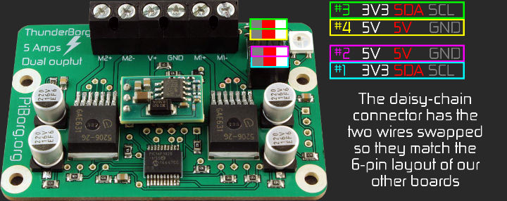
Once that is connected make sure the script is set back to bus 1 and try again :)
phwagwa
Sat, 06/16/2018 - 22:48
Permalink
still did not work
hi,
we went ahead and connected a ground wire, and still no luck...
thanks in advance for any other ideas!
piborg
Sun, 06/17/2018 - 12:21
Permalink
Testing the connection
There are a few possible causes for this particular problem. Some more diagnostic information should help us figure our what is wrong.
Could you run this command:
sudo i2cdetect -y 1and show us what result you get.
phwagwa
Mon, 06/18/2018 - 02:47
Permalink
diagnostics results
hi, thank you for trying to help -- attached are the results you asked for.
piborg
Mon, 06/18/2018 - 17:46
Permalink
I2C connection problems
The wiring all looks correct, the problem seems like the I2C signals are not getting to the ThunderBorg.
The LED coming on is a good sign, it means the ThunderBorg is getting powering up and the on-board code is running.
There are two likely explanations at this point:
I would suggest we try and use WiringPi to see if the Pi has faulty GPIO pins.
First disconnect all of the wires from the GPIO to the ThunderBorg.
Next download and build the WiringPi code:
After it has built run the GPIO pin tester:
You should see some diagnostics after pressing ENTER:
PinTest
=======

This is a simple utility to test the GPIO pins on your Raspberry Pi.

NOTE: All GPIO peripherals must be removed to perform this test. This
  includes serial, I2C and SPI connections. You may get incorrect results
  if something is connected and it interferes with the test.

This test can only test the input side of things. It uses the internal
pull-up and pull-down resistors to simulate inputs. It does not test
the output drivers.

You will need to reboot your Pi after this test if you wish to use the
serial port as it will be left in GPIO mode rather than serial mode.

This test only tests the original pins present on the Rev A and B. It
does not test the extra pins on the Revision A2, B2 nor the A+ or B+

Please make sure everything is removed and press the ENTER key to continue,
or Control-C to abort...

          The main 8 GPIO pins  0: 7:  OK
                The 5 SPI pins 10:14:  OK
               The serial pins 15:16:  OK
                  The I2C pins  8: 9:  OK
Hopefully all of the end lines say
OK, otherwise the GPIO is not working correctly on the Raspberry Pi itself.After the test restart the Raspberry Pi to reset the GPIO pins back to their standard behavior.
Pages